| home | builders | Search |
| builders ➜ Control Panel - Raspberry PI Shelf |
| TARPN Brew and Home Brew Components | |||
|---|---|---|---|
| Almost everything on this list can be cheaper or easier in quantity. Work with a group! | |||
| Quantity | Description | Source | |
| (1) | Raspberry PI 3B, 3B+, 4B 1Gbyte, 4B 2Gbyte, 4B 4Gbyte. |
Mouser,
Digikey,
Newark,
ChicagoDist, Adafruit, Canakit | |
| (1) | TARPN Control Panel, board + parts | More info [TARPN] | |
| (1) | DC-DC regulator device with 5.2 V adjustable output like the DC-DC DROK Power Supply Module LM2596 | More info [TARPN] | |
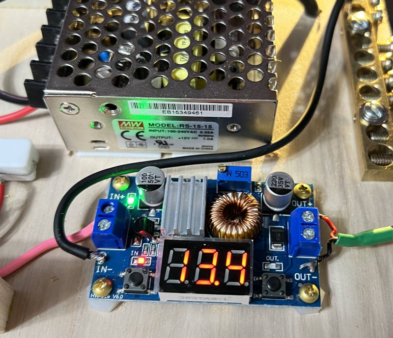
| (1) | Meanwell RS-15-15 14.2volt variable power supply. | More info [TARPN] | |
| (1) | Assembled main-power/backup-power switchover and charger circuit | More info [TARPN] | |
| (1) | 3d printed NinoTNC mounting plate. | inquire on TARPN list, or Discord server | |
| Store-Bought Parts | |||
| (1) | 2 Amp SLA battery PS-1220 prefered | Amazon B078T35B14 | |
| (1) | 6 or 7 inch short USB cable | Amazon B07PYT3VM3 | |
| (4) | 3M Scotch 311DC Heavy Duty 1-Inch Double face tape for mounting the Meanwell power supply. | Amazon B07DM7VDNL | |
| 15 feet | VELCRO Brand - Sticky Back Hook and Loop Fasteners – 15ft x 3/4in Tape | White - for attaching Raspberry PI to the shelf | Amazon B000GR9X28 | |
| 6-foot | of hookup wire, 16 to 20 AWG. BNTECHGO 20 gauge 5 colors | Amazon B06Y58W228 | |
| (1) | 8 position (or more) Square D ground bus bar | Amazon B06Y58W228 | |
| (4) | female Crimp-on lugs for the battery and for the back of the Control Panel. Amazon Lugs Assortment kit | Amazon B078PMWNJC | |
| (20) | 4 inch Tie Wraps | Amazon B087MKMSDY | |
| (10) | Fancy adhesive clips to grab wires and hold them in place. | Amazon B01HR9VS4I | |
| Nuts/Bolts/Screw Hardware | |||
| (4) | M3x0.5mm thread Hex Nuts - for inserting into the mounting plate. | McMaster-Carr 91828A211 | |
| (4) | M3x0.5mm thead 8mm long machine screws - - for screwing the Raspberry PI onto the mounting plate | McMaster-Carr 92000A118 | |
| (9) | 1/2 inch #4 brass phillips decorative rounded head wood screw Raspberry PI shelf to top of Control Panel rails - and mount regulator to shelf | McMaster-Carr 98685A330 | |
| (4) | 3/8 inch #4 brass phillips decorative rounded head wood screw Control Panel into rails | McMaster-Carr 98685A540 | |
| (4) | insulating spacers to space the regulator off the shelf. Use large-gauge nylon nuts as spacers. | McMaster-Carr 90089A305 | |
| Wood Pieces | |||
| (2) | control panel rails - 1+1/4 inch x 2 inch (or longer) Blondwood plywood blocks | (Lowes hardware) | |
| (1) | Raspberry PI mounting plate - 3 inches by 5+1/4 inches out of 1/4" plywood | (Lowes hardware) | |
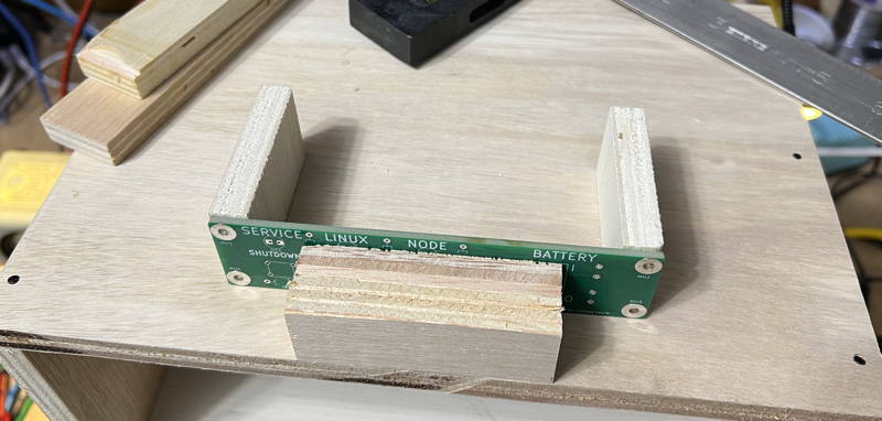
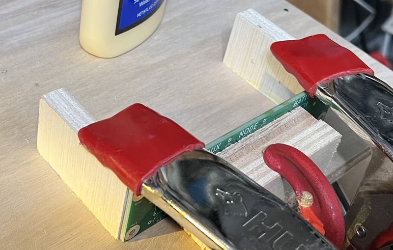
Make it easy to get the control panel rails into the desired location by putting guidance blocks ("chocks") to the left and right of the control panel mount rails..
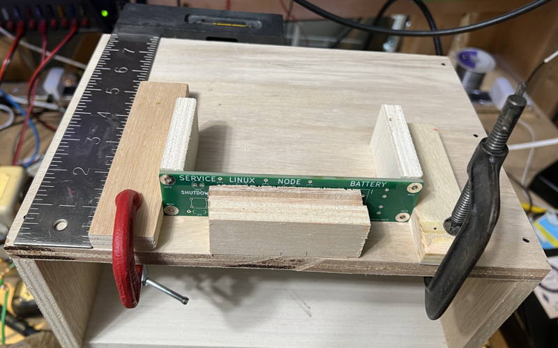
 Put glue on the bottom of the two control panel rails and wipe smooth with a finger.
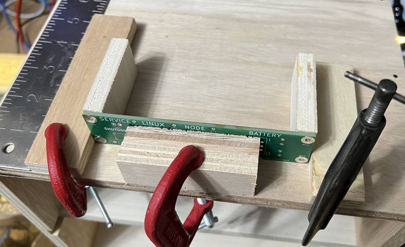
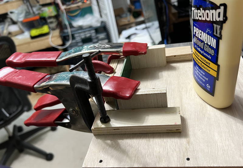 Remove the side chocks to reveal glue that spread out from under the two pieces.
Clean up the visible glue with your finger.
Remove the side chocks to reveal glue that spread out from under the two pieces.
Clean up the visible glue with your finger.
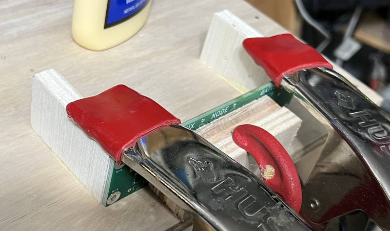 That looks better.
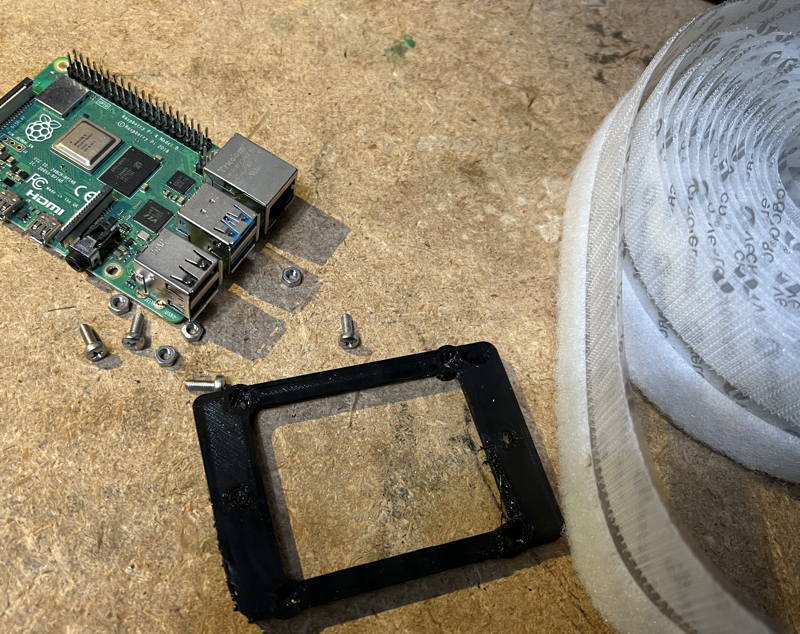
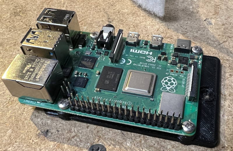
While the glue is drying, find your plastic Raspberry PI plate, velcro, M3 nuts and screws, and the Raspberry PI.
The M3 screw will not fit through the hole in the Raspberry PI
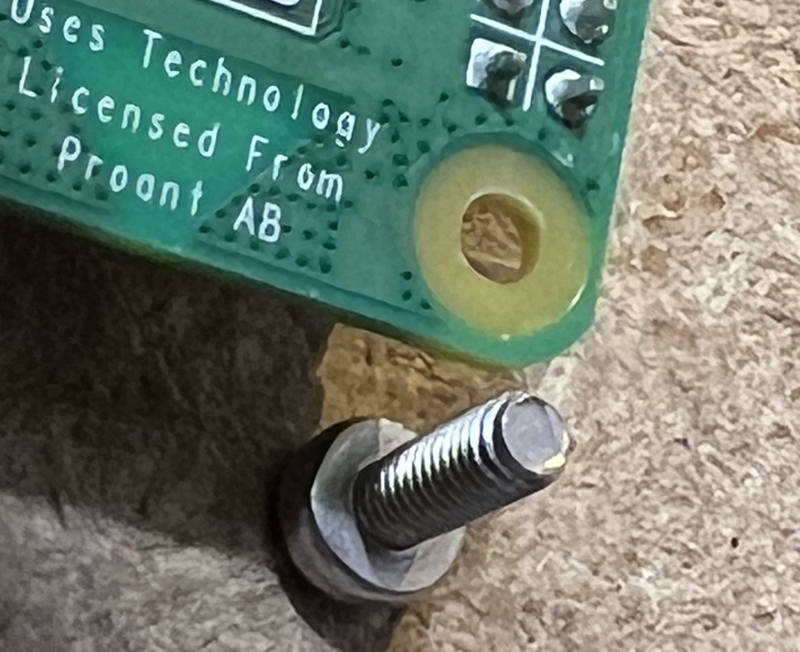
CAREFULLY use a 1/8th inch drill bit and variable speed drill to enlarge the 4 holes in the Raspbery PI to fit the M3 screw.
A reemer is actually prefered because it is easier to control.
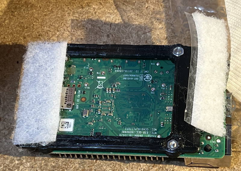
This picture shows the desired result.
In order to get this, you first need to press or hammer or squeeze with pliers to press the four nuts into the bottom of the mounting plate.
Try to line up the hex nut with the hex shaped hole in the bottom of the plate, and then squeeze with pliers.
The plates are a little fragile, but they are also cheap.
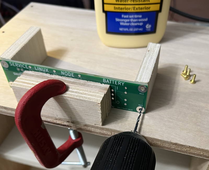
 Now that an hour has elapsed and the glue has dried:
Using a 1/16 inch drill bit, pre-drill the wood-screw holes for the Control Panel.
Drill a hole that is something less than 1/2 inch deep as close to the center of the mounting hole as you can.
You'll eventually be mounting a finished control panel using 3/8 inch #4 wood screws.
Now that an hour has elapsed and the glue has dried:
Using a 1/16 inch drill bit, pre-drill the wood-screw holes for the Control Panel.
Drill a hole that is something less than 1/2 inch deep as close to the center of the mounting hole as you can.
You'll eventually be mounting a finished control panel using 3/8 inch #4 wood screws.
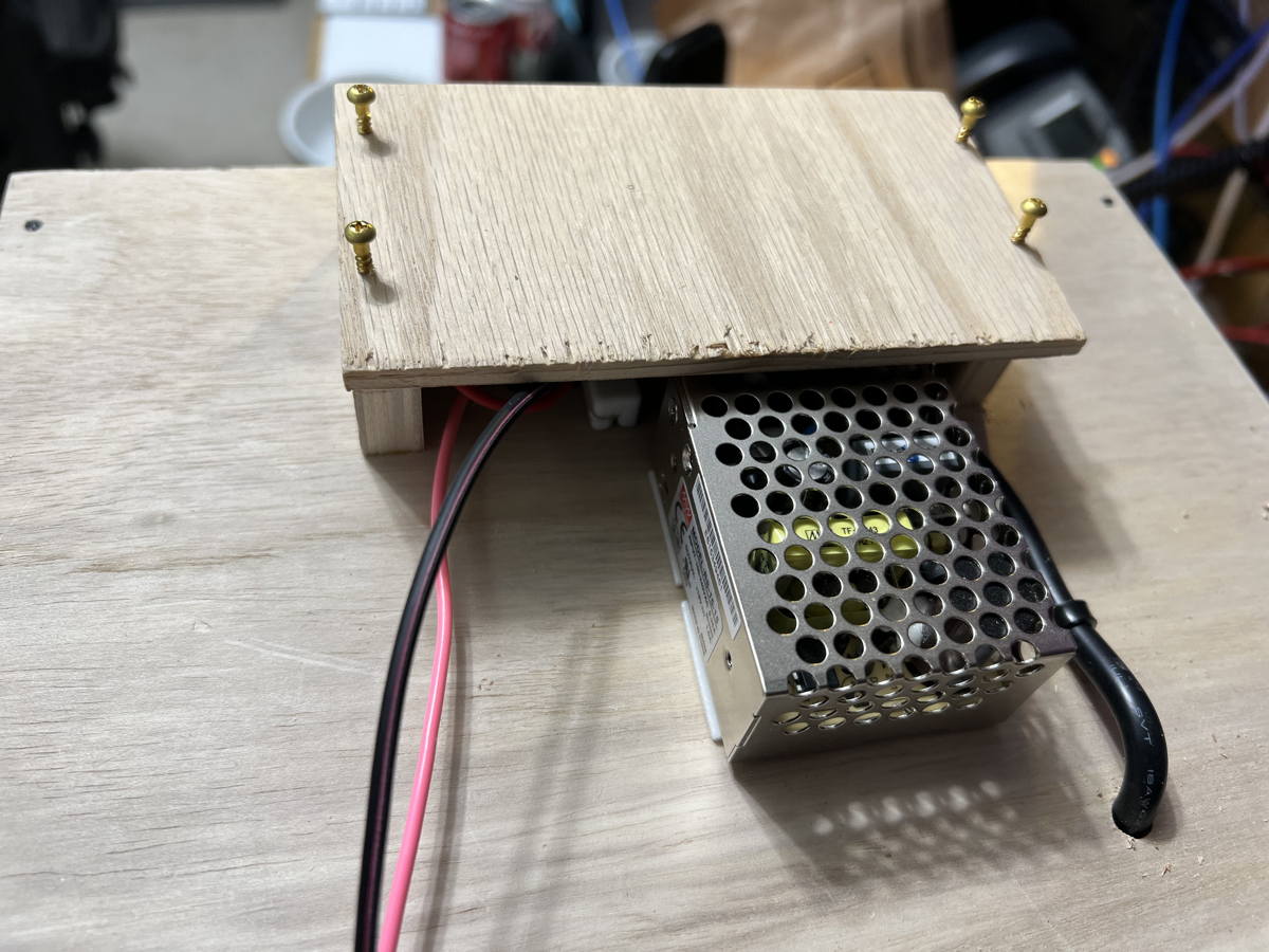
 Cut a piece of wood about 3 inches by 5+1/4 inches out of 1/4" plywood.
This will be the Raspberry PI mount and we will use wood screws to attach this to the top of the control panel mount rails.
Cut a piece of wood about 3 inches by 5+1/4 inches out of 1/4" plywood.
This will be the Raspberry PI mount and we will use wood screws to attach this to the top of the control panel mount rails.
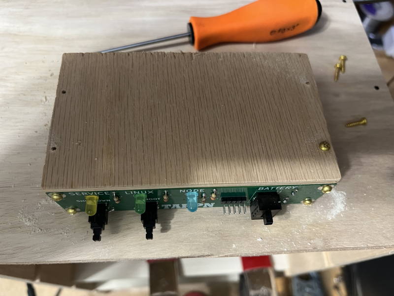
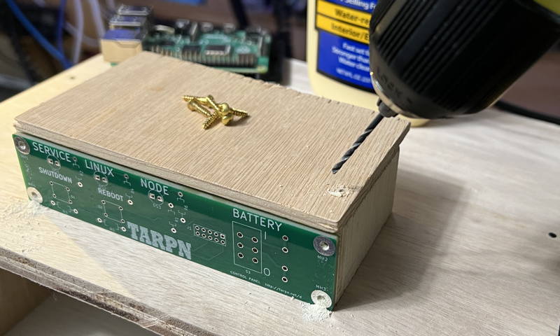 Assemble the control panel. TARPN Control Panel
Using a 1/16th inch drill bit, drill 1 starter hole through the Raspberry PI wooden mounting plate into the control panel rail and apply one 1/2 inch #4 wood screw.
Assemble the control panel. TARPN Control Panel
Using a 1/16th inch drill bit, drill 1 starter hole through the Raspberry PI wooden mounting plate into the control panel rail and apply one 1/2 inch #4 wood screw.
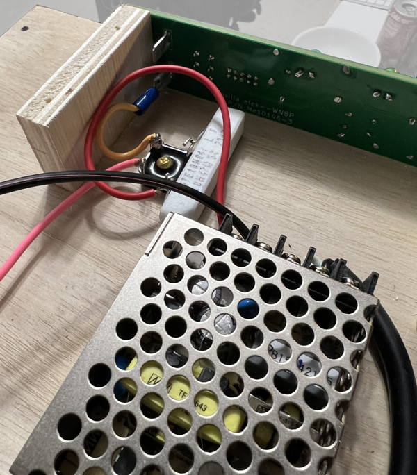
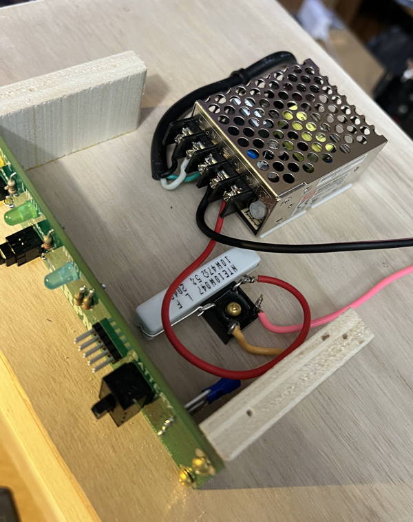
 Remove Raspberry PI shelf and work on the Meanwell supply and the bridge rectifier switchover/charge circuit.
|
|
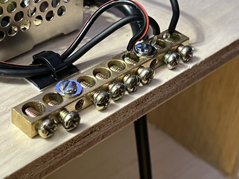
 Install a ground bus screw terminal with at least 8 screw down locations.
Put it on the back edge of the shelf.
Install a ground bus screw terminal with at least 8 screw down locations.
Put it on the back edge of the shelf.
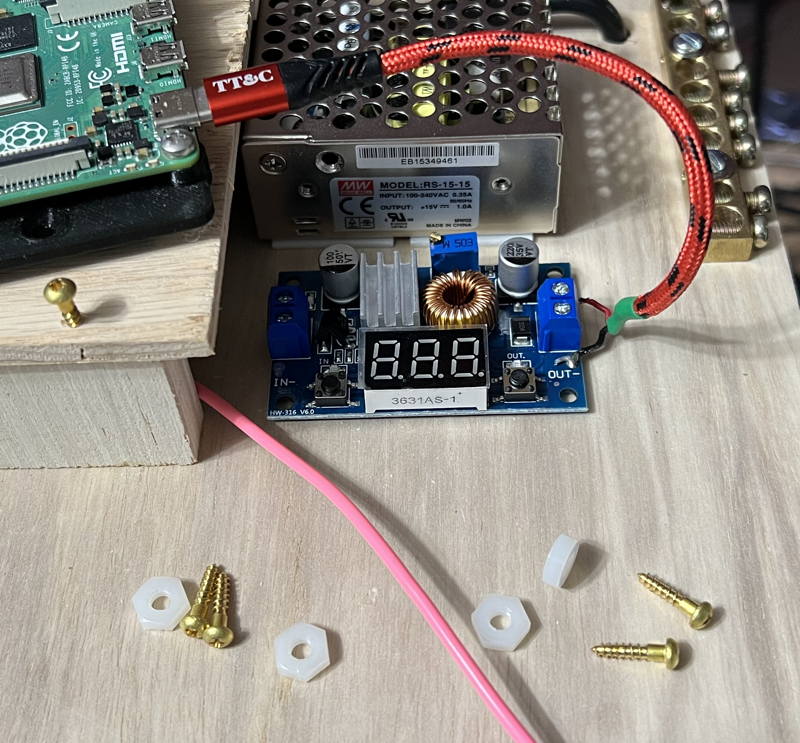 Pre-drill a hole to secure the regulator using your 1/16th inch drill bit.
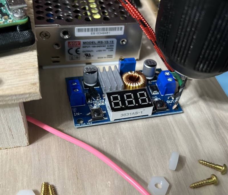 Pre-drill the remaining 3 holes. Loosely secure the opposite corner, again with the spacer of some kind.
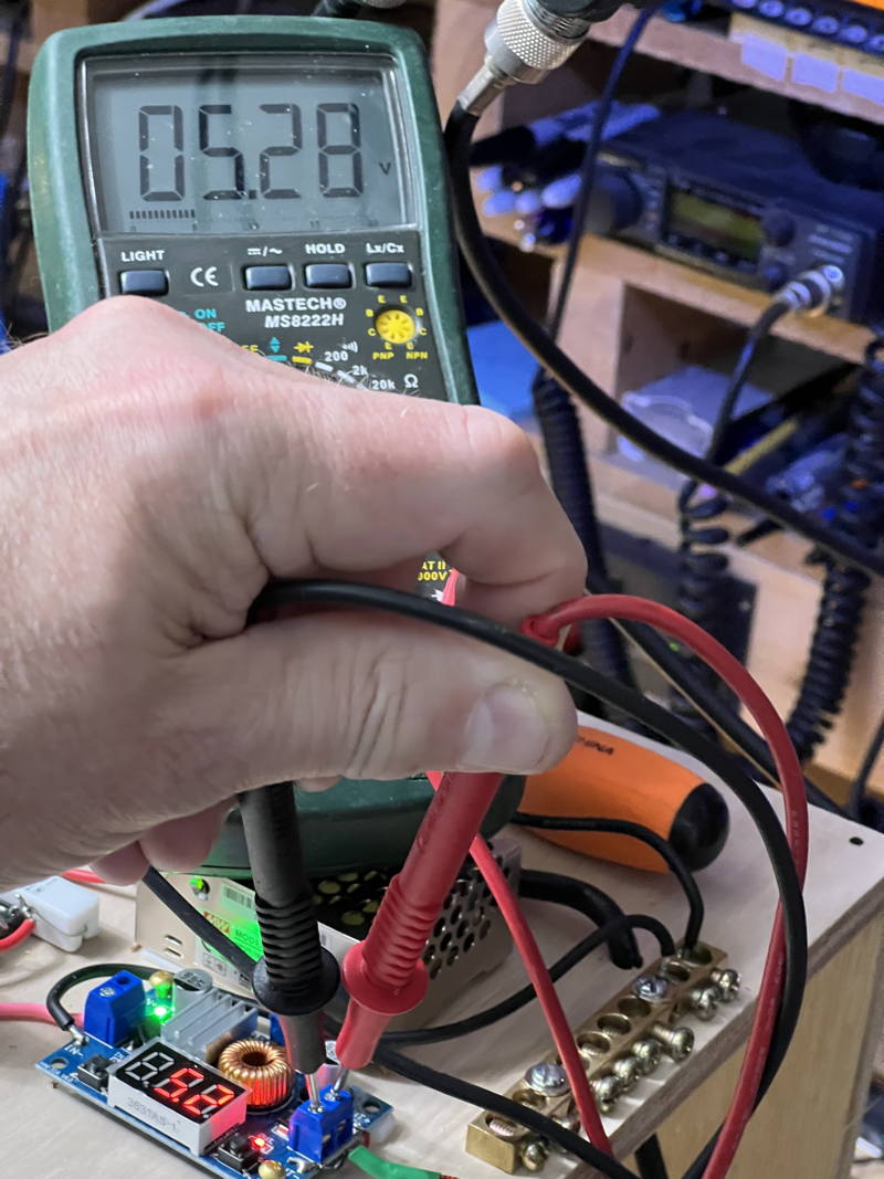
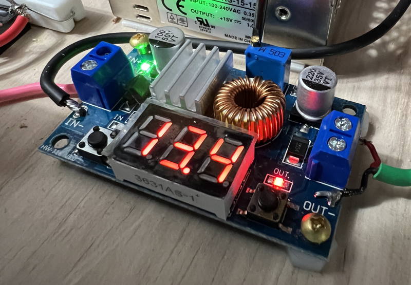 Using a small flat head screwdriver, turn the multi-turn pot counterclockwise.
Pay attention to the voltage.
It won't change at all at first.
When you hit the critical range, it moves rather quickly.
Using a small flat head screwdriver, turn the multi-turn pot counterclockwise.
Pay attention to the voltage.
It won't change at all at first.
When you hit the critical range, it moves rather quickly.
 That will do.
 Now screw down all 4 corners of the regulator using 1/2 inch #4 wood screws and the same spacers you used before.
 Place the battery where it will be permanently located.
If you are using the Jay-box, put the battery in the side-car with the lugs against the front of the box.
Plus should be up so it is protected against some stray wire touching it under the side-car.
The lugs should be front so they can't touch the metal HP power supply.
Make a custom length orange jumper with lugs on each end to connect the + terminal of the battery to the back of the control panel.
This will connect the battery + terminal to the lug on the back of the control panel.
Place the battery where it will be permanently located.
If you are using the Jay-box, put the battery in the side-car with the lugs against the front of the box.
Plus should be up so it is protected against some stray wire touching it under the side-car.
The lugs should be front so they can't touch the metal HP power supply.
Make a custom length orange jumper with lugs on each end to connect the + terminal of the battery to the back of the control panel.
This will connect the battery + terminal to the lug on the back of the control panel.
 Make a custom length black jumper with lug on one end, and tined wire on the other for connecting the - (minus) terminal of the battery to the ground bus.
 Turn off the battery using the Control-Panel switch, for now.
Screw down the four 1/2 inch #4 wood screws to hold the Raspberry PI shelf to the Control Panel rails.
Turn off the battery using the Control-Panel switch, for now.
Screw down the four 1/2 inch #4 wood screws to hold the Raspberry PI shelf to the Control Panel rails.
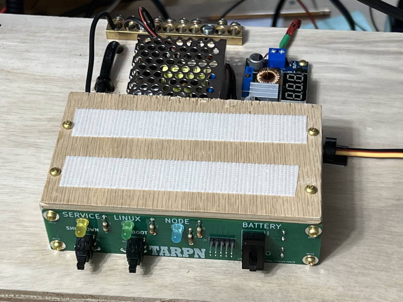 Place the Raspberry PI, bracket down, and USB connectors to the left, down on the velcro pad.
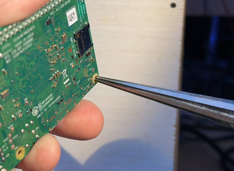
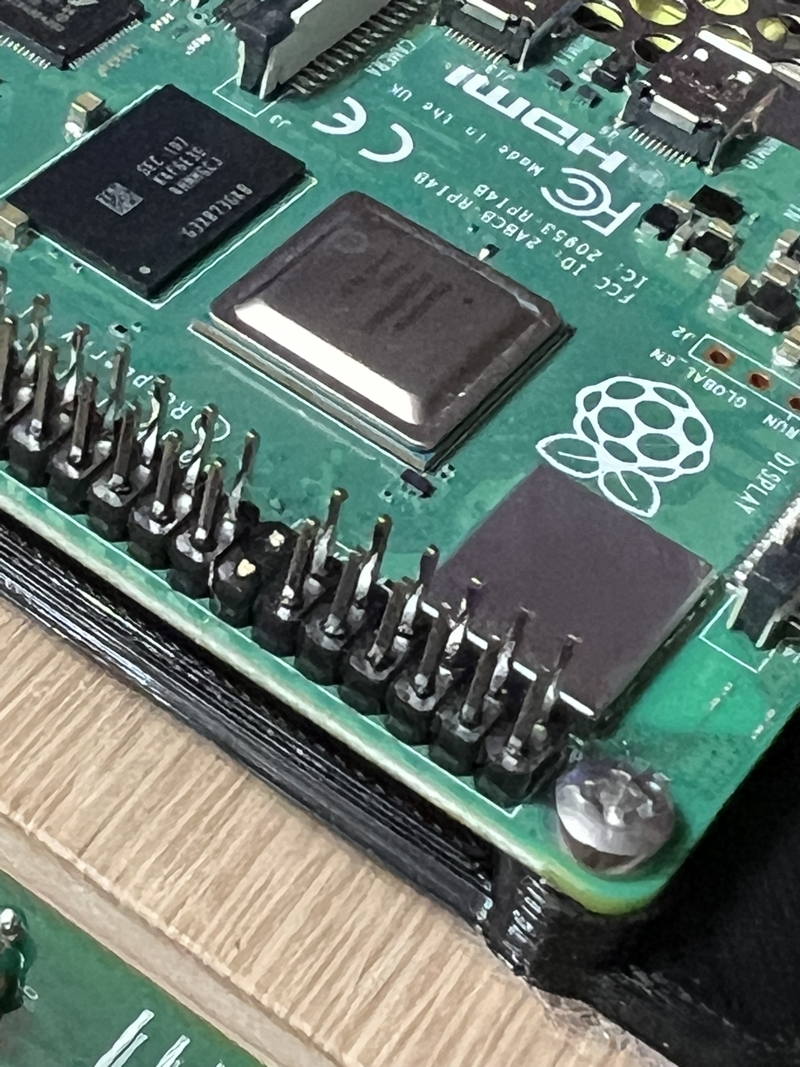
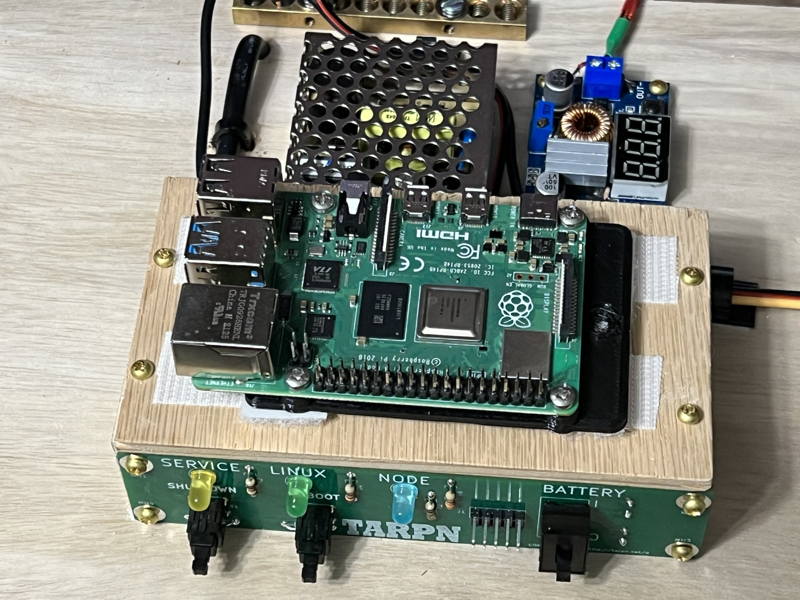 Now we're going to break four pins off of the Raspberry PI's 40-pin auxiliary connector to make room for the 2x5 ribbon cable connector.
There must be space on both sides of the connector.
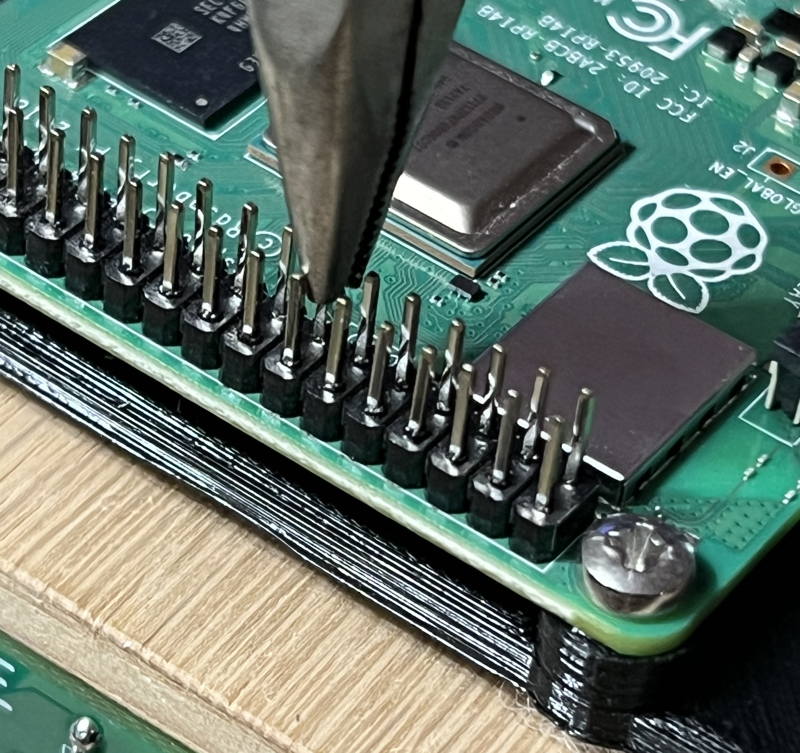
Row 7, measured from the SDcard end of the Raspberry PI must be removed, as well as row 13.
See the next several images for the steps I use to do this.
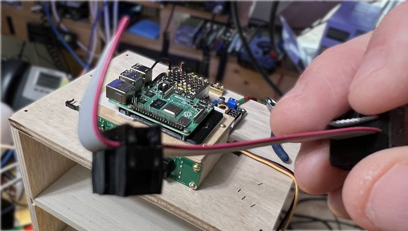
Grab first pin, on row 7.
We'll bend this with a long nose plier.
Now we're going to break four pins off of the Raspberry PI's 40-pin auxiliary connector to make room for the 2x5 ribbon cable connector.
There must be space on both sides of the connector.
Row 7, measured from the SDcard end of the Raspberry PI must be removed, as well as row 13.
See the next several images for the steps I use to do this.
Grab first pin, on row 7.
We'll bend this with a long nose plier.
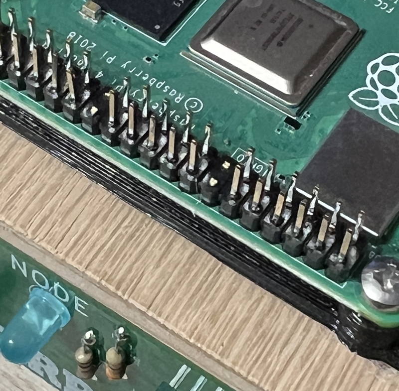
 You'll need to wiggle the pin toward the CPU and then straight back up, and repeat several times.
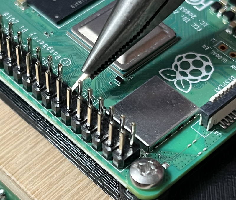 7th row now removed
 On the 13rd row, break both pins
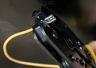
 Cut a 4 inch piece of ribbon cable.
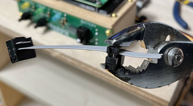
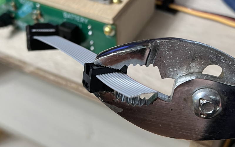
 If you have enough extra on the ends, wrap it around the connector and install the straign relief part of the IDC connector.
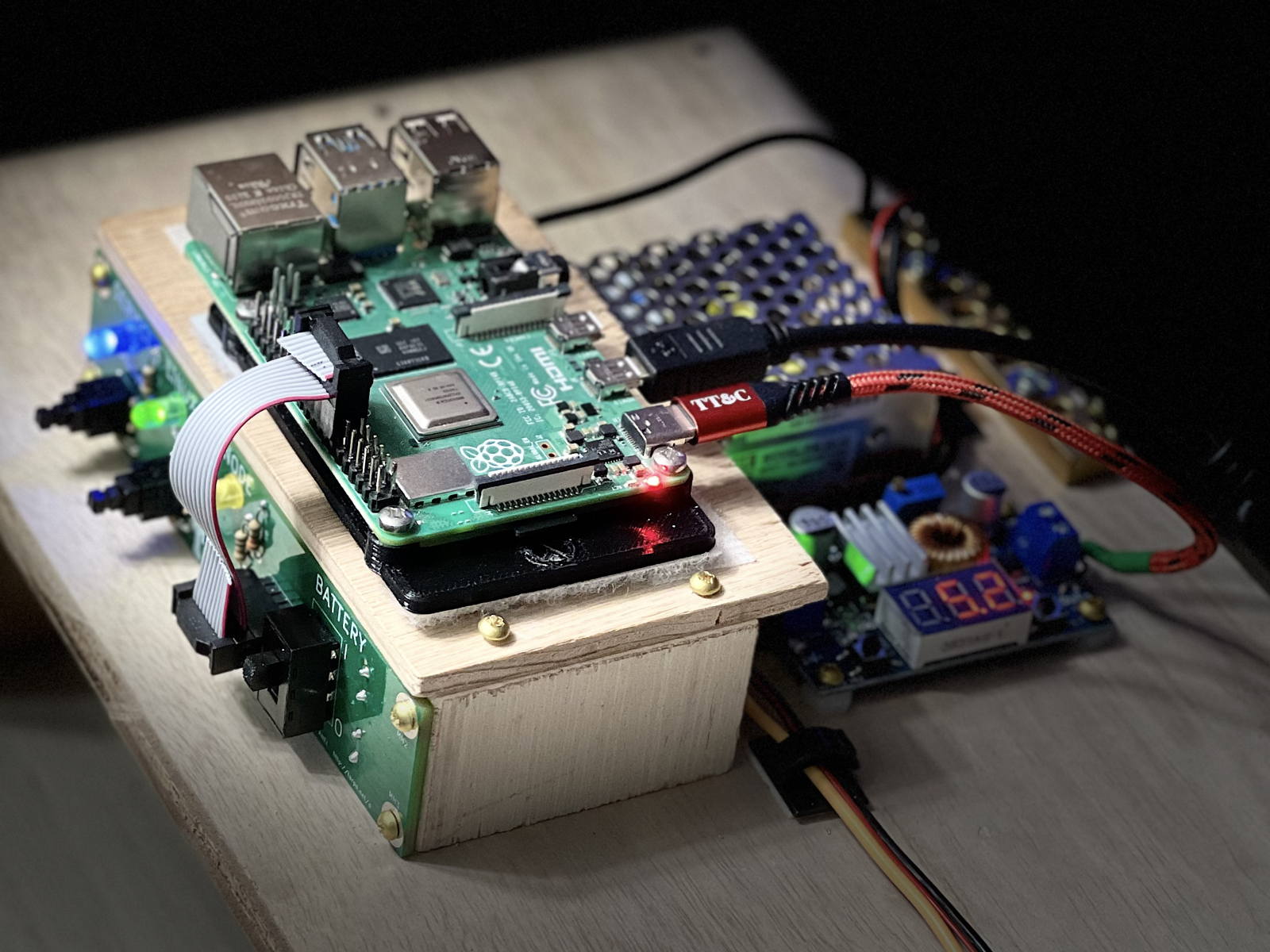
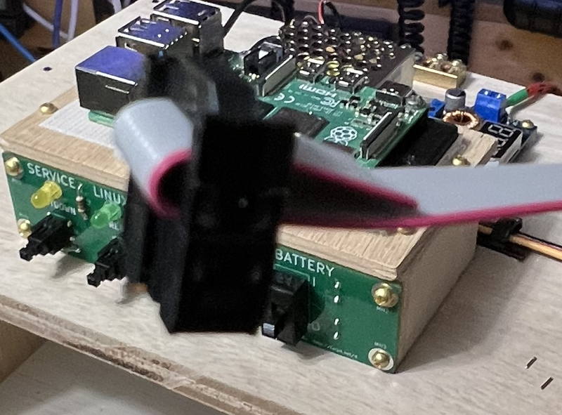 Attach ribbon cable to control panel and Raspberry PI as shown
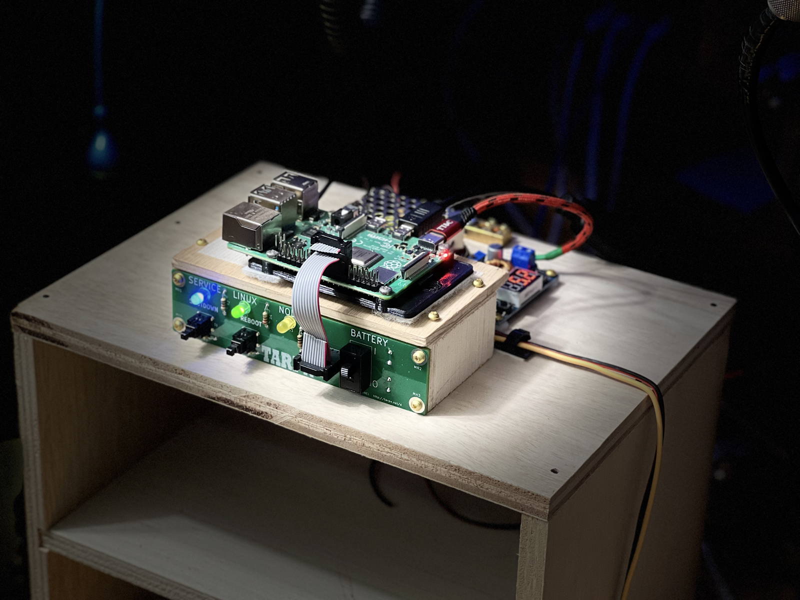
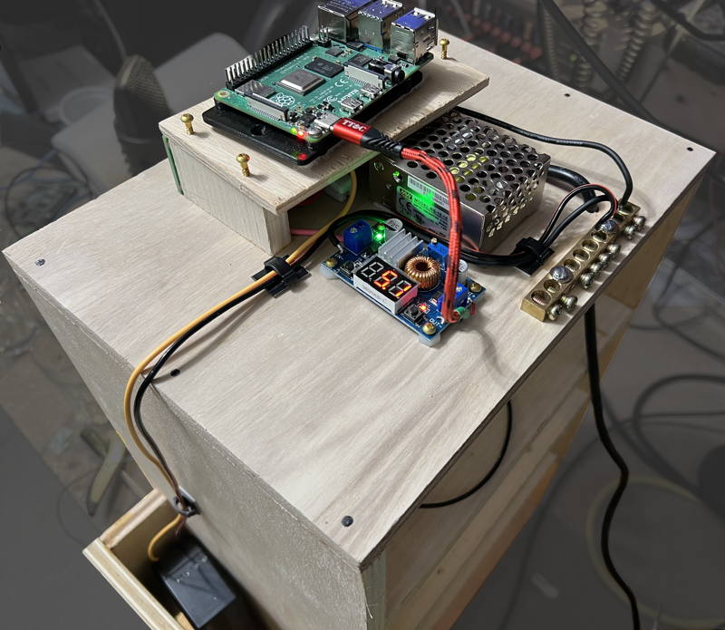
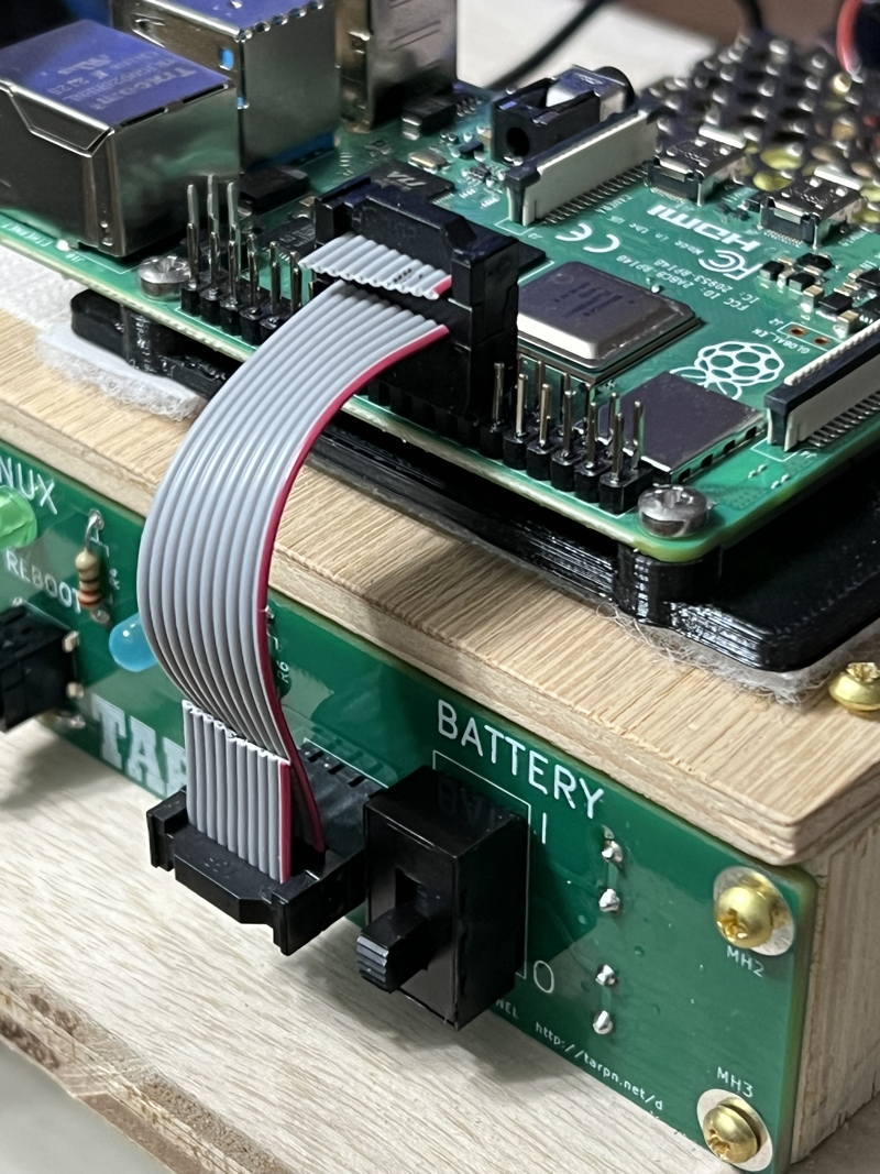 Your Raspberry PI shelf is complete.
If you have an SDCard node already built, you can power it up and see the control panel light up.
Otherwise,
initialize your Raspberry PI to be a TARPN Node.
Your Raspberry PI shelf is complete.
If you have an SDCard node already built, you can power it up and see the control panel light up.
Otherwise,
initialize your Raspberry PI to be a TARPN Node.