| home | builders | Search |
| builders ➜ TARPN Hardware ➜ Control Panel Info ➜ Control Panel 2020-A Assembly |
This document refers to the 3-LED Control Panel. There is a newer version that is very similar except that it has a 4th LED labelled 3.3V. The assembly documentation for the new control panel is here: Control-Panel-2024
Specifications may change without notice.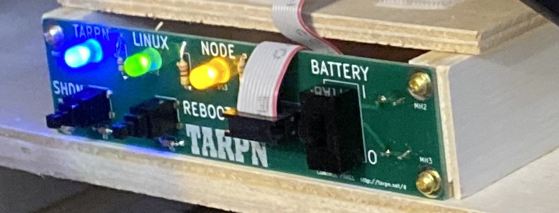
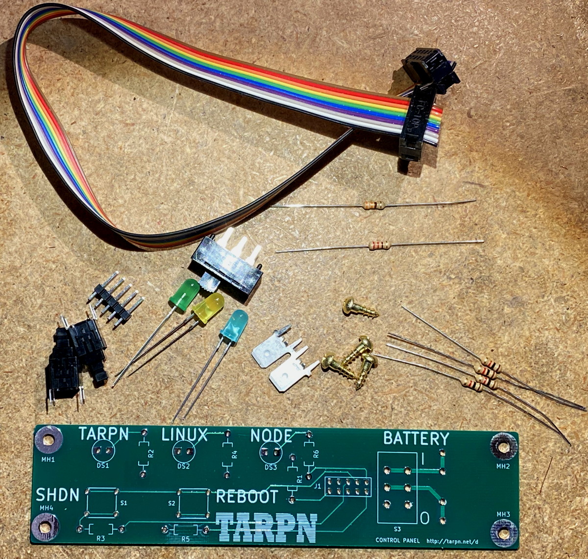
| ⇒ | Excepting the battery wiring lugs, all of the parts are inserted from the silk-screened side of the board, i.e. from the side on which the white writing is printed. |
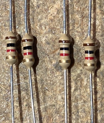
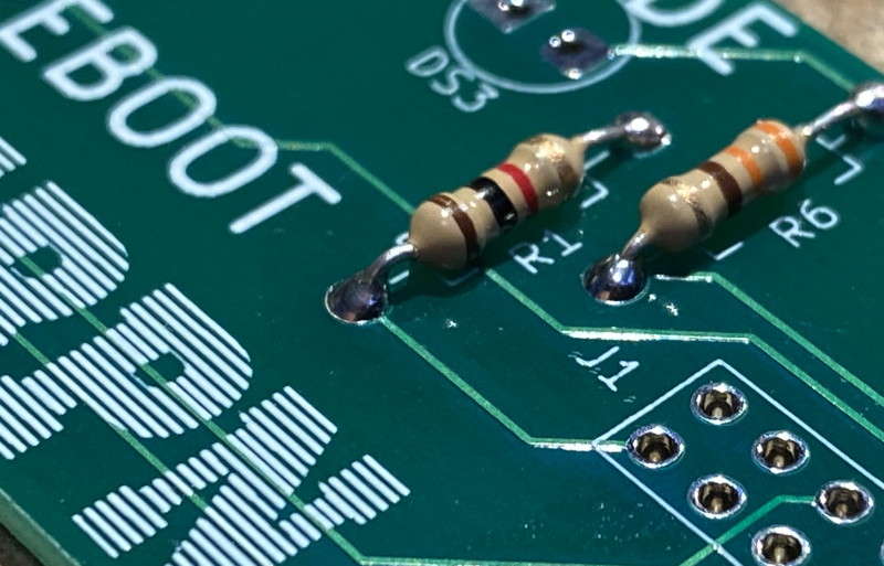
| ⇒ | The resistors are non-polarized. You can put either end of the resistor in either of the two holes. |
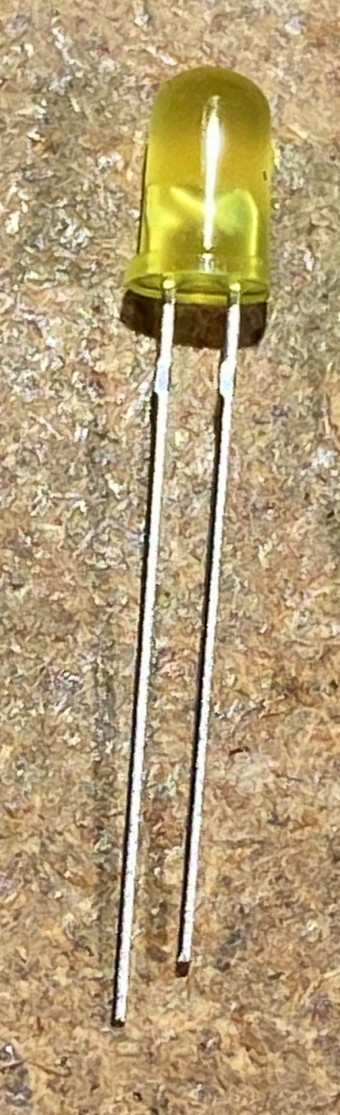
| ⇒ | The LEDs are polarized. The instructions are specific. |
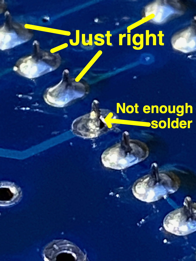
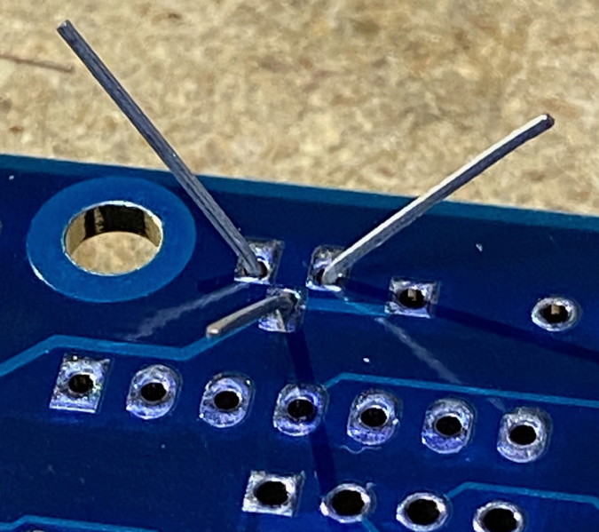 Inspect the leads to make sure the solder comes up over the lead for a visible amount.
Cut the lead at the wire, not the solder.
The solder is your friend.
What you do NOT want is a lead which is not making good electrical contact with the hole.
Inspect the leads to make sure the solder comes up over the lead for a visible amount.
Cut the lead at the wire, not the solder.
The solder is your friend.
What you do NOT want is a lead which is not making good electrical contact with the hole.
 Here's the control panel PCB's schematic. Click to load the PDF.
|
There are two different circuits in this device.
The first is a switch which connects or disconnects the VCC to the battery.
The switch is capable of interrupting up to 3 A of current.
Use crimp-on lugs on the wire to the battery.
See the Robust Power for Raspberry PI page.
The second part of the circuit is the connection to the Raspberry PI.
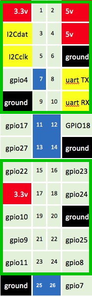
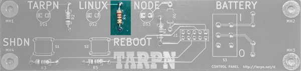
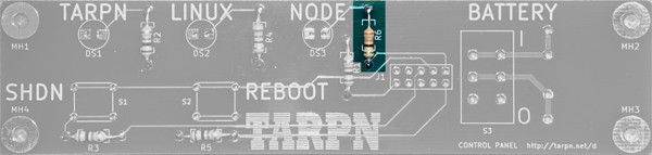
The key element is a jumper between GPIO pins. A script runs on the Raspberry PI called pi_shutdown_background.sh. That script initializes the GPIOs used for the control panel and looks for a short between GPIOs 8 and 11, which map to pins 23 and 24 of the expansion connector. See the image below. There are two GPIOs configured as inputs. Pull them to 3.3v (through a resistor) and pin 19 will cause a Linux shutdown, and pin 16 will cause a Linux reboot. Note that neither of these affect the power to the Raspberry PI. There are three outputs which are useful for driving LEDs. Again, make sure the current does not exceed the drive power of a Raspberry PI GPIO. ### toward SDcard ### output high if LINBPQ up GPIO 22 GPIO 23 input. if high, do reboot ### 3V3 PWR GPIO 24 output high if LINUX ### Shutdown when High input GPIO 10 GROUND ### .5hz output GPIO 9 GPIO 25 NC ### /======= input GPIO 11 GPIO 8 output >>====\ ### | toward USB | ### | | ### \===============================================/When I made the diagram to the right we were using the TNC-PI which connected to the upper 10 pins. The lower boxed set of pins would be for the PWRMAN board, or the One-Button-Shutdown board. The control panel presented here is based on the One-Button-Shutdown design. Larry WN8P did the layout for the Control Panel board based on my One-Button-Shutdown design. You're going to have to do something to make the ribbon cable fit on the appropriate 10 pins. I cut the expansion connector pins 13, 14, 25 and 26 using a diagonal cutter. Be careful to not let the pins fly or get in your eye. It could be bad. |
|
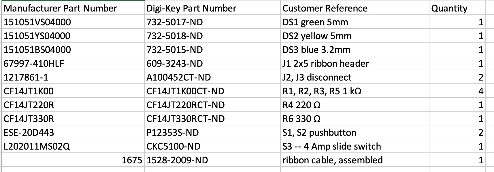
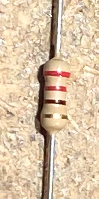
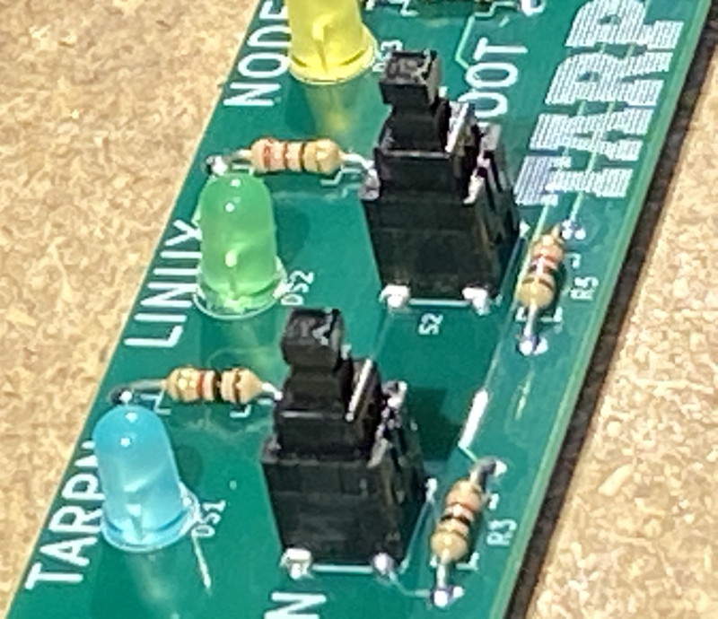
| 1 | R1, R2, R3, R5 | 1 k Ω 5% 1/4 W resistor
 |
R1 serves as a link between a GPIO output and a GPIO input.
The raspberry PI uses the presence of this link as a signal that the control panel is hooked up.
R2 is used as a current limiting resistor for the blue LED DS1. Resistors are not polorized so you can put either end in either hole. It might help to bend the wires loosely from the ends of the parts. Leave about 1/10th of an inch before a slight curve. If you bend the resistor leads sharply, it is hard to insert them. 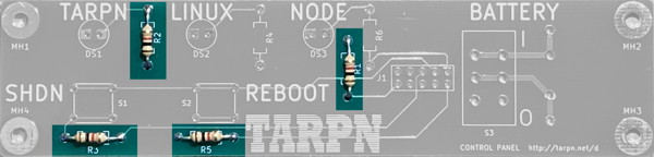
R3 and R5 are current limiting resistors for the two switches, S1 and S2, respectively. |
| 2 | R4 | 220 Ω 5% 1/4 W resistor
 |
R4 is a current limiting resistor for the green LED, DS2.
 |
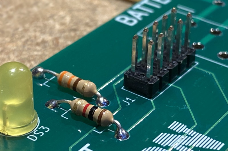
| 3 | R6 | 330 Ω 5% 1/4 W resistor
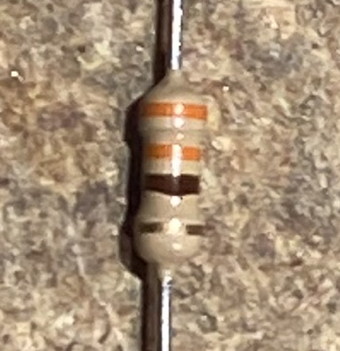 |
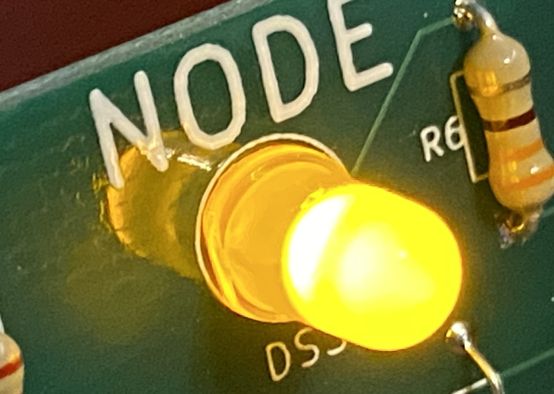
R6 is a current limiting resistor for the yellow LED, DS3.
 |
| 4 | DS1 DS2 DS3 | LEDs blue, green, yellow
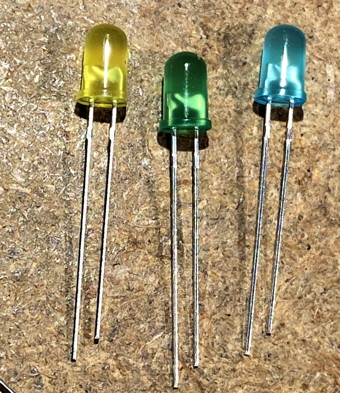 |
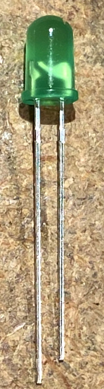
The LEDs are polarized. Follow the instructions here.
All 3 LEDs are driven by Raspberry PI GPIO through a current limit resistor. Since the LEDs each have a different efficiency and brightness, the current limit resistors were chosen to tune the LED to an appropriate level so the LED brightnesses appear to be balanced. Note: The short wire on each LED, which is toward the flat edged side of each LED's plastic housing, goes to the pad on the left, and that is the ground connection. The long LED lead goes into the hole where the signal-wire from the resistor is connected to the LED. Feel free to install all 3 LEDs, bending their leads out to hold them in place, and then solder. |
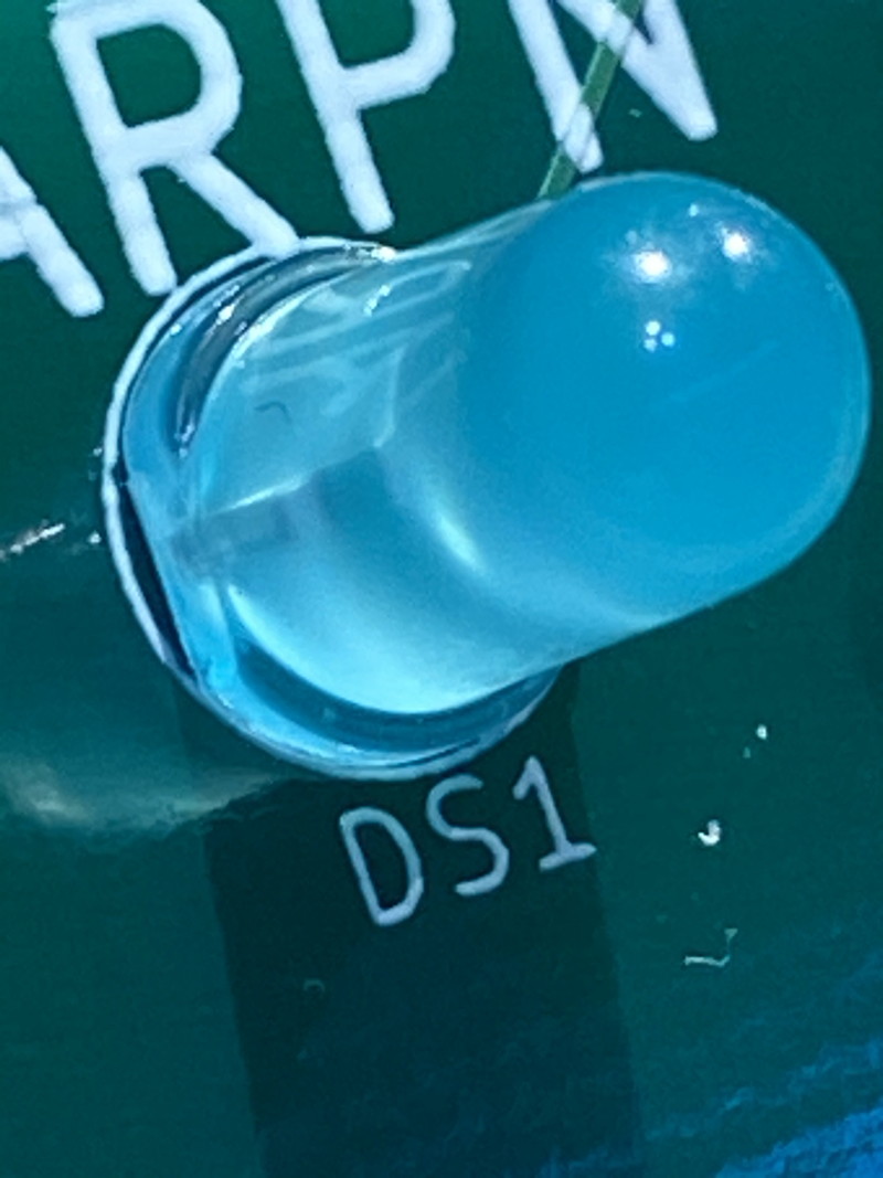
| DS1 | Blue
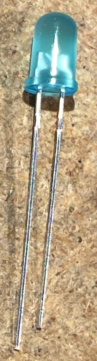 |
DS1, Blue, is driven through a 1 K Ω resistor, more than 2x the resistance of either of the other LEDs.
For some reason, blue LEDs are naturally brighter?
Install the LED so it is flush with the board (no space between the bottom of the LED and the PCB) and so the squared off side of the LED body is to the left. 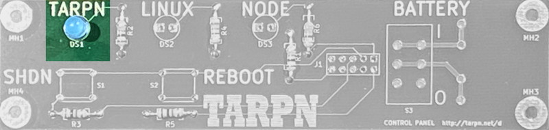
| |
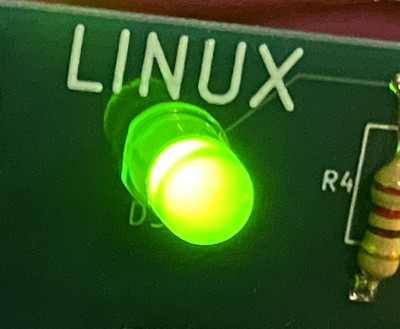
| DS2 | Green
 |
DS2, Green, is the dimmest of the LEDs, so we feed it through the lowest value resistor of the three, 220 Ω.
Install the LED so it is flush with the board (no space between the bottom of the LED and the PCB) and so the squared off side of the LED body is to the left. 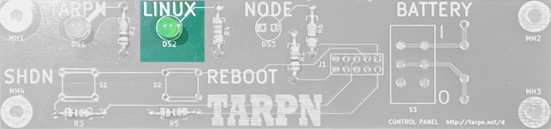
| |
| DS3 | Yellow
 |
DS3, Yellow, is fed it through a 330 Ω resistor.
Install the LED so it is flush with the board (no space between the bottom of the LED and the PCB) and so the squared off side of the LED body is to the left. 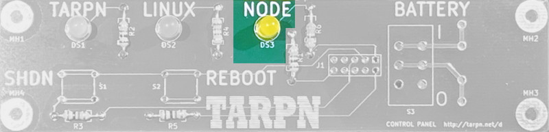
|
| 5 | J1 | 10 pin 2x5 0.1" spacing socket
 |
J1 is used for a ribbon cable connection to the Raspberry PI.
I suggest soldering one pin on the bottom of the board, probably in one corner, then, with the bottom of the board up, apply some pressure on the 2x5 connector, and heat up the one pin. Now rock the board so the 2x5 connector is appropriately flush and allow the solder to cool. Inspect and make sure the connector is placed properly. Now solder the other 9 pins. 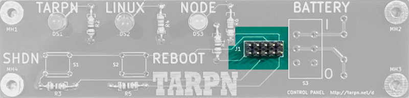
 |
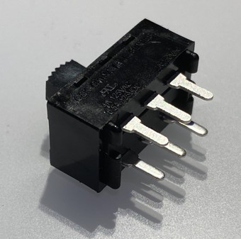
| 6 | S1 and S2 | push button switch
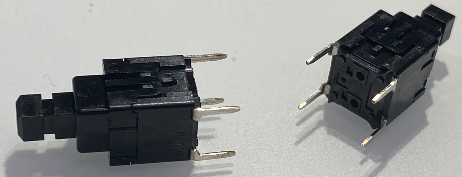 |
These two switches each are connected to GPIOs on the Raspberry PI and when pushed will pull the associated GPIO low (through a 1K resistor).
If running the TARPN pwrman service, the service will take action to shut down, or reboot, Linux, as appropriate.
The switches go in cleanly if they are lined up with the hole.
There is a wrong way to put them in, but they don't fit very easily in the wrong way.
2 right ways, 2 wrong ways. The smooth sides of the switch body face left and right. Solder one corner, then, while heating the corner, force the switch to seat flush with the board. Then solder the other 3 legs. Repeat for the other switch. 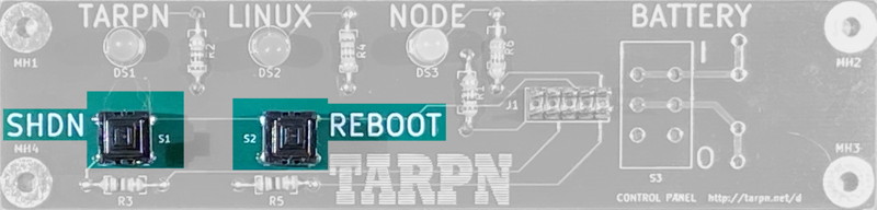
 |
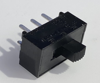
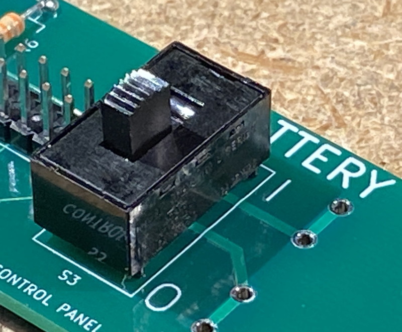
| 7 | S3 | 3 A slide switch
|
We had a problem with the 2nd board order where the switch and ribbon cable were too close together.
The solution was to place a ribbon cable connector over the 2x5 header before soldering down this switch.
There is a potential interference problem between the ribbon cable connector and this switch. 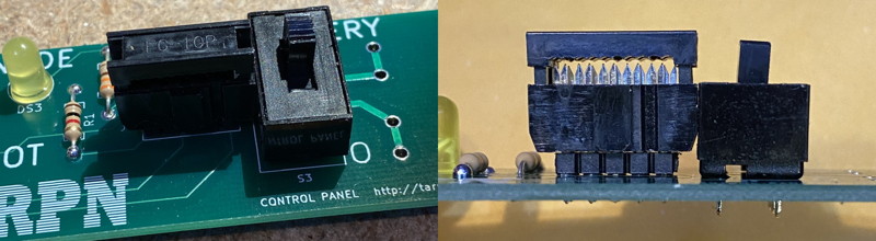 Placing the connector on first reduces the problem.
In the next build of this board we'll make a little more room.
Sorry about this.
This switch connects or disconnects the two battery power lugs.
We'll be soldering the lugs in the next step.
The lugs are in circuit with a lead-acid (SLA or Gel-Cel) battery.
The switch is rated 3 amps which is the maximum the battery should be sourcing to the 5.2V power supply.
Placing the connector on first reduces the problem.
In the next build of this board we'll make a little more room.
Sorry about this.
This switch connects or disconnects the two battery power lugs.
We'll be soldering the lugs in the next step.
The lugs are in circuit with a lead-acid (SLA or Gel-Cel) battery.
The switch is rated 3 amps which is the maximum the battery should be sourcing to the 5.2V power supply.
There is no on vs off orientation for the switch body, itself. Solder one of the middle pins, then while heating the pin, force the switch to seat flush with the board. Then solder the other pins. 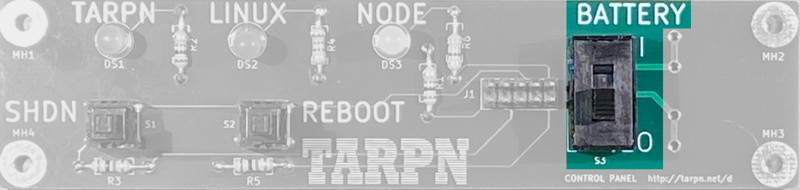
 |
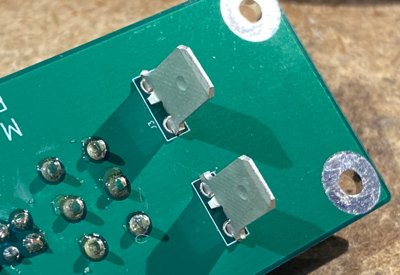
| WARNING!!!! This next step is where most of the O.M.G. mistakes have been made. The J2 and J3 lugs stick out the back of the board and are soldered from the front. This is opposite of every other part you've soldered onto this board. |
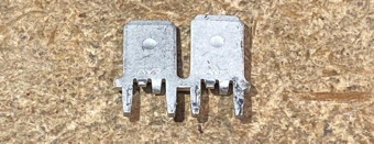
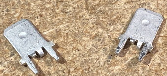
| 8 | J2 and J3 | Battery Lugs
|
These parts come attached to one another.
I just wiggled them back and forth on the joint until they came apart.
Make sure the two pins on each part don't get bent much, or adjust them so they are parallel after separating the parts.
These get pushed into the board from the back, right next to the big slide switch. Solder them in front the front of the board. There will be some resistance to pushing them into the board. The point of these lugs is that your battery wiring from the switchover circuit to the gel-cel will pass the battey PLUS lead through the switch. This lets you disconnect the battery after you shut-down your Raspberry PI's Linux system. 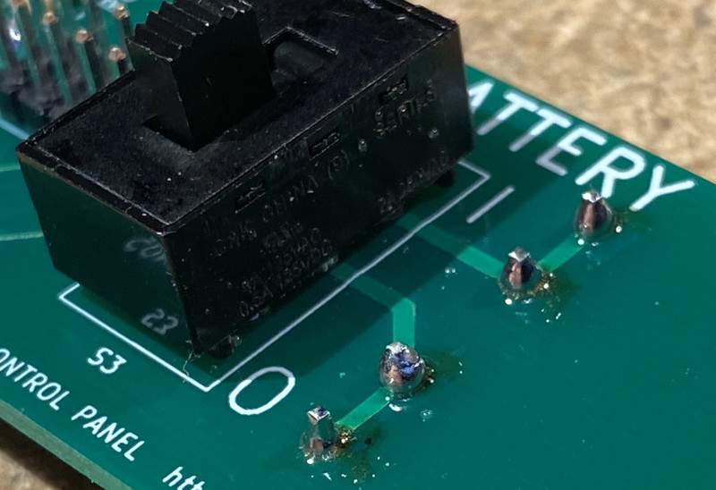
 |
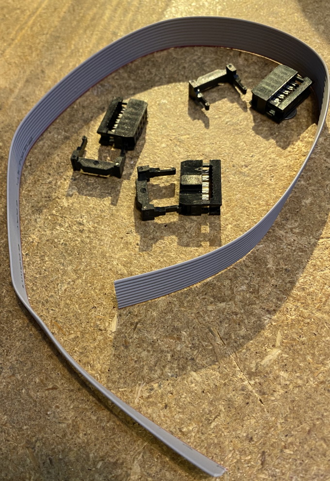
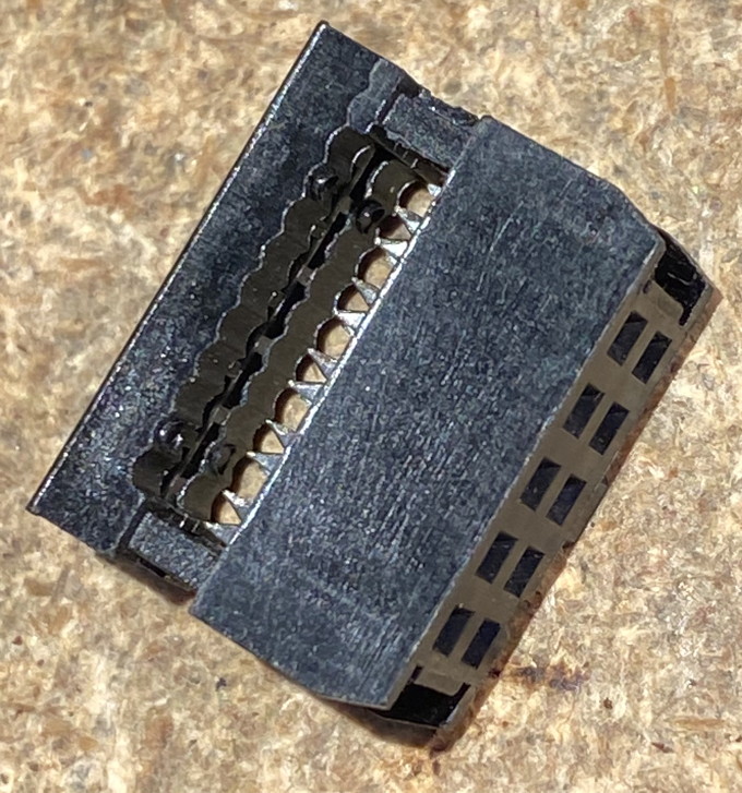
| 9 | ribbon | Assemble the ribbon cable.
|
You are supplied with 3 Insertion Displacement Connectors (IDC) and a foot or more of ribbon cable. You'll only use 2 of the connectors. The 3rd connector is included for practice or in case a 2nd try is required. The length of the wire required is specific to your needs. It is ideal that the ribbon be shorter than 6 inches if you are using UHF radios nearby so don't leave much slack lying around if you don't have to. The wire will run from your control panel to the Raspberry PI. The orientation of the connector on the cable relative to how it plugs in is critical. For simplicity, clamp the connectors on the same side of the ribbon cable. For instructions on installing the IDC connector, see this link: Ribbon Cable Construction Note that I often don't use the extra piece of the ribbon cable connector. That piece helps for strain relief but that hasn't been necessary for our application. |
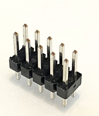
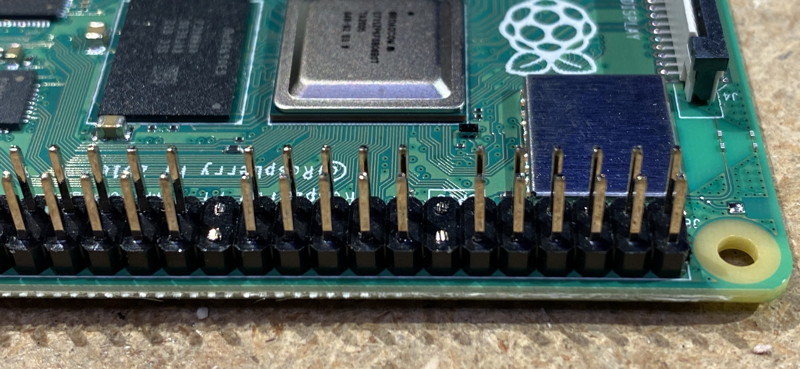
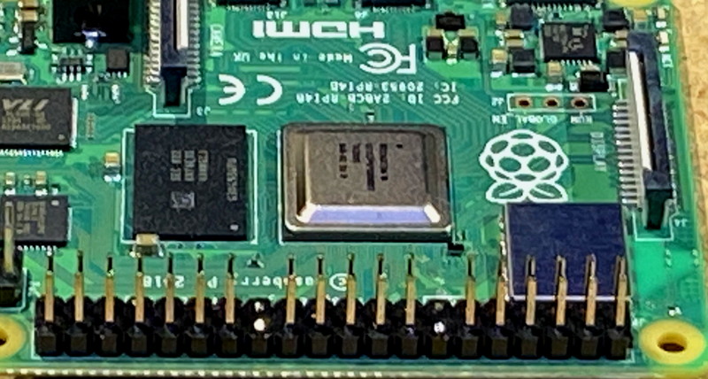
| 10 | Pi Aux Cuts | Modify the Raspberry PI.
Cut two sets of two pins on the expansion connector to make room for the IDC plug to fit over thte appropriate 10 pins.
Count 6 pins down from the corner, then cut two pins across, leaving 2x6 intact.
Then count down 5 more pins, and cut two pins across, leaving 2x5 intact.
Carefully observe the photo.
 One option to making this mod is to buy a stacking connector and then modify the stacking connector.
Digikey link for stacking header
One option to making this mod is to buy a stacking connector and then modify the stacking connector.
Digikey link for stacking header
|
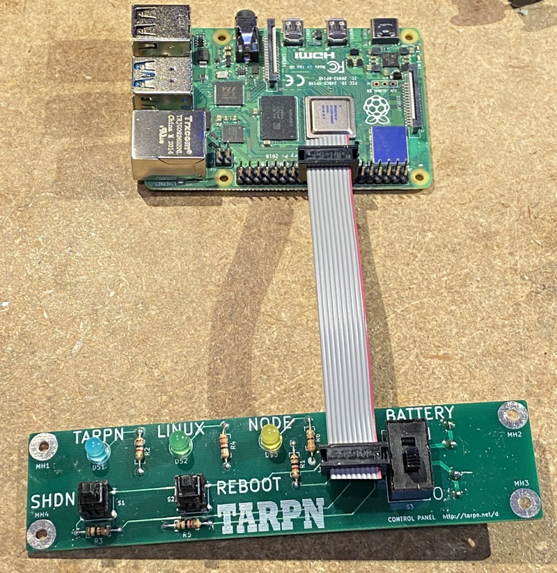
| 11 | Final | Assembly | Plug the IDC ribbon cable from the control panel to the Raspberry PI.
Carefully observe the orientation.
The cable goes up over the top of the control panel to the near edge of the Raspberry PI near the expansion connector, and then right onto the Raspberry PI expansion connector's pins 15 through 24.
|
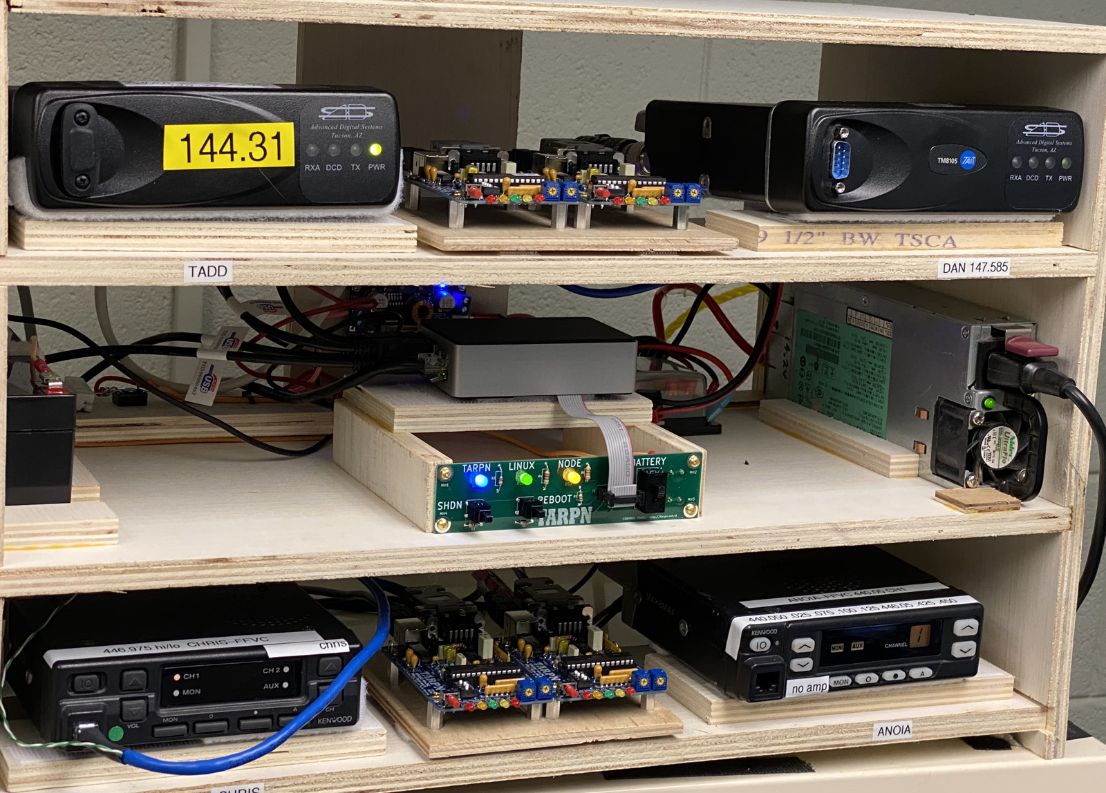
pi@taddpacket:/var/log $ tail -f tarpn_pwrman.log

 pi_shutdown_background.sh --VERSION-- b009 - start:Wed 24 Mar 2021 11:41:51 PM EDT
 23:41:51 up 64 days, 23:05,  4 users,  load average: 0.16, 0.16, 0.12
gpio export facility exists
Wed 24 Mar 2021 11:41:51 PM EDT  PWRMAN loopback cable fail at startup on first -1- echo test
Wed 24 Mar 2021 11:41:51 PM EDT  PASS - ONE-BUTTON loopback cable pass at startup on first -1- echo test
PASS - ONE-BUTTON loopback cable pass at startup on first -0- echo test
Wed 24 Mar 2021 11:41:52 PM EDT  Wed 24 Mar 2021 11:41:52 PM EDT  PASS - ONE-BUTTON loopback cable pass at startup on 2nd -1- echo test
Wed 24 Mar 2021 11:41:53 PM EDT  PASS - ONE-BUTTON loopback cable pass at startup on 2nd -0- echo test
Wed 24 Mar 2021 11:41:53 PM EDT  ####  ONE-BUTTON loopback cable PASS at startup
If the system is running correctly and the Control Panel is functional, the blue light should flash once per second, and the green light should be steady on. The yellow light is on if the node software is running. If you press and hold the SHDN button for one complete blue-light blink-cycle, the blue light will flash two times slightly faster than usual, then hold, and then the Raspberry PI will shut-down turning out all of the lights. The green light will go out about 10 seconds before the PI goes to hold-for-poweroff. Now it is safe to remove power from the Raspberry PI.