See also:
Control Panel/Raspberry PI Shelf
See also:
Robust Power For Raspberry PI
See also:
Purchasing and wiring a Meanwell RS-15-15
See also:
Assembling the Switchover Circuit
5.2 V Regulator
|
The Raspberry PIs are most happy with 5.2 V power feed via the USB input to the Raspberry PI.
They are also most happy with a glitch free uninteruppted 5.2V.
Even a 1/1000th of a second glitch to below 5V seems to lead to SDcard corruption.
The solution, since we're running on 12V (mostly) for the radios, is to take the 12V and regulate it down to 5.2V, and then to back-up the 12V source.
The cheap way to get 5.2V from 12V is to use off-the-shelf 12V to 5.2V devices that are made in Asia.
These can be from $2 to $16.
Amazon B07N3QT628
The ideal solution would have screw terminals for power input, and a USB connector for power output.
We were able to buy such a device for several years but the manufacturar, DROK, revised the model a couple of years ago with one whose USB output, while still variable, is disabled by default when power is applied to the inputs to the device.
It requires a menu operation to turn the power on.
This is not useful to us.
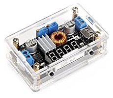
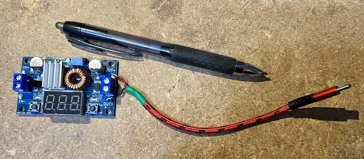
There are several off the shelf boards available from hundreds of random name-changing vendors via Amazon, eBay, Aliexpress, that are specified to take 12-15V or wider and regulate it down to a variable output including 5.2V and put it out on screw terminals or solder pads.
In all cases we now have to find a connection into the Raspberry PI.
Again, USB input to the PI is most convenient.
|
This is the elusive discontinued DROK USB-output variable supply
It's key feature is the built-in always-on USB power output connector.
Beware that the new DROK USB output regulator has a default-off USB output.
The key visible difference between the models is the good model has a 4 digit LED display and the new (bad) model has an LCD display.
|
So now, besides finding an appropriate regulator, we need to put together a USB cable that is two wires in, and USB plug out.
The cheapest way to do this is to take a USB to USB cable and cut one end off.
The issue now becomes figuring out which wire in the USB cable connects to the 5V bus on the PI and which connects to Ground.
Unfortunately, the selection of a regulator, and the analysis of the USB cable, must fall to the individual node-box robust-supply builder.
Perhaps, optimally, your club can get together and do a group buy and then solve the problem once for multiple builds.
The description to search on is
"
DC-DC DROK Power Supply Module LM2596"
I recommend not using price as your sole selection criteria.
Some price between $4 and $20 can be expected.
If you are going to do a group project, it may be worth buying several models and then once mastery is achieved, do a group buy immediately before the shifty suppliers shift supplies, or shift supplier name to another shifty sounding name.
Warning..
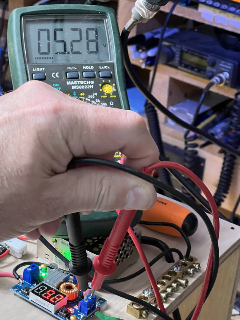
Adjust the output voltage to 5.2 V before plugging in the Raspberry PI.
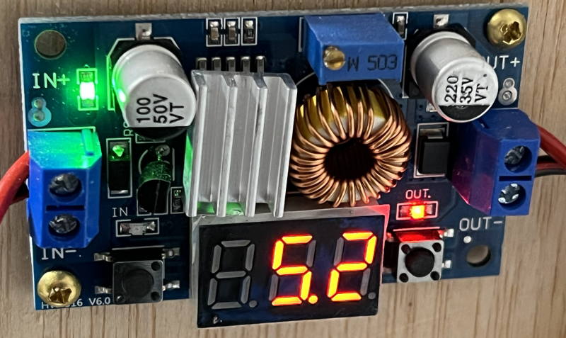
This is the unit I have been using when I could not get the now-discontinued unit.
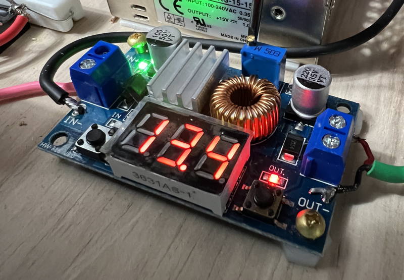
This unit has both screw terminals and solder pads for input and output, and has a display that can (with only about 0.2V accuracy) show the input and output voltage.
It costs about $15 from Amazon, cheaper from other suppliers. But beware the cheaper suppliers.
Amazon has a hassle free return policy.
There are some cheaper devices from DROK on Amazon.
Some of those may be as good as this one. YMMV.
I picked up 20 of these boards by accident from an Aliexpress shifty vendor whose advertisement showed the desirable unit (with always-on-USB) and was asking $4 each.
So cheap! So I ordered 20 of them.
What I received 6 weeks later was a box full of this unit (same regulator/controller chip, but no USB output).
I called a foul on them to Aliexpress and, though it took a bit of arguing and incriminating photos/screenshots, Aliexpress made the vendor give me back my $80+ but the vendor didn't want to pay shipping to send the 20 units to Asia, so I got to keep them.
USB Cable modification
During final assembly you'll need to hook up a USB cable to the PI and to the output of the supply.
First we have to make a custom USB cable that attaches to the output of the regulator.
What I did is cut an off-the-shelf-cable such that there is about 6 inches of wire between the Raspberry PI end and where I cut.
Then strip the wire outer jacket back.
Insert a heat shrink tube, about an inch long, over the wire and push it away up toward the PI plug end.
Now strip back the 4 wires inside the cable.
Plug the USB cable into the Raspberry PI.
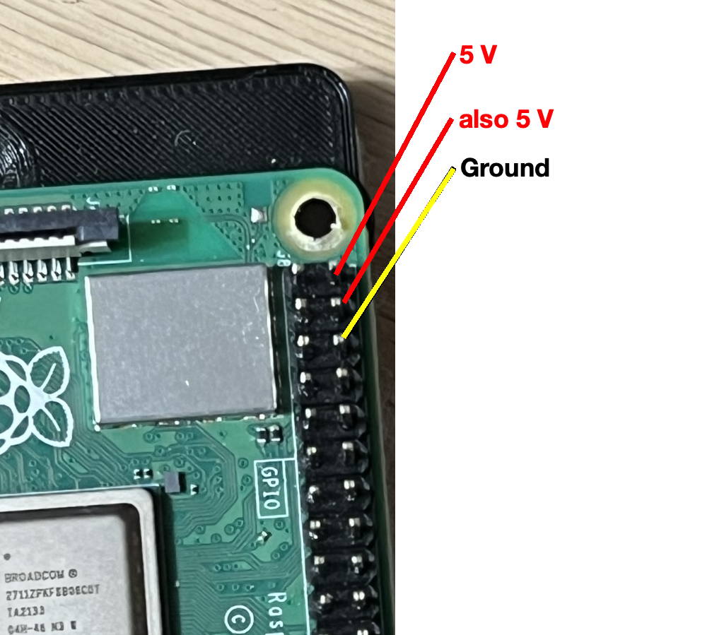
Refer to this diagram for test points on the Raspberry PI:
Use the V-O-M in ohms setting to check which wire is ground by measuring the resistance from the ground pin on the Raspberry PI's 40 pin expansion header to each of the 4 wires..
The lowest resistance should be nearly 0 ohms and that will be the ground wire.
Solder the discovered ground wire to the regulator's -V terminal on the OUTPUT side of the regulator card. (or tin and screw the wire to the output)
Use the V-O-M to find the 5 V wire, again by measuring ohms to the Raspberry PI's 40 pin header.
Solder or screw the 5 V wire to the supply at the +V terminal on the OUTPUT side of the regulator card.
After the wire cools where you soldered, move the heat shrink over the stripped end of the wire and shrink it to cover the unused two wires on the USB cable.
|
|
|
You will want the USB wire from your regulator to the PI to be really short.
6 inches is a good length.
If longer, the voltage at the PI will vary with processor or accessory load.
During PI operation using the desktop display, you could see a lightning bolt on the upper right of the display during boot, and that would indicate you are under-volts.
|

|
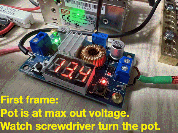
You should definitely use a V-O-M when setting the regulator's output voltage and
do not have the USB cable plugged into the Raspberry PI until you have set the regulator's output voltage.
Beware that the multi-turn potentiometers may only have a useful range in the middle of the 10 or 20 turn mechanical range.
That means that you may be turning the pot counterclockwise, i.e. down, several full turns before the output moves at all.
This is probably because the output range is 30 volts or so, but it won't affect the output until the adjusted-voltage is less than the input voltage, which in this case is going to be around 12 V.
There is a small LED above each button that indicates whether you are seeing the INPUT (left) or the OUTPUT (right LED) voltage on the display.
Exercise the two buttons .
One button will turn the display on and off.
The other button selects whether you are displaying the INput voltage or the OUTput voltage.
Both voltages should read your power supply voltage.
Configure the regulator to show the OUT voltage.
Using a small flat head screwdriver, turn the multi-turn pot counterclockwise.
Pay attention to the voltage.
It won't change at all at first.
When you hit the critical range, it moves rather quickly.
That will do.