See also:
Control Panel/Raspberry PI Shelf
See also:
5.2 V Regulator
See also:
Robust Power For Raspberry PI
See also:
Purchasing and wiring a Meanwell RS-15-15
Assembling Robust Power Switchover Circuit
This page talks about the bridge rectifier and resistor which is the cheap but critical part of the Robust Power supply.
The Meanwell power supply feeds two diodes, one that feeds the Raspberry PI, and one that feeds power to charge the battery.
The battery feeds one diode that feeds the regulator that powers the Raspberry PI.
The diodes make it so only one of the Meanwell or the battery is feeding current into the Raspberry PI's regulator, depending on which has the higher voltage.
If the Meanwell is powered, then it will win and will put power to the regulator. If the Meanwell is NOT powered, then the battery will drive the regulator.
|
|
Parts for the switchover/trickle charge circuit
Parts list:
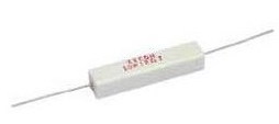
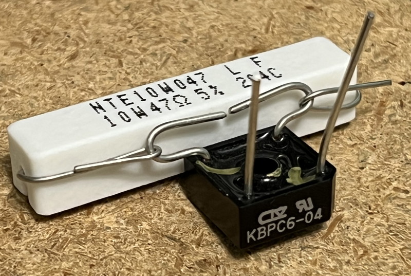
- 45 to 100 Ohm, 5 or 10 Watt resistor -- the photos below show a 10watt resistor.
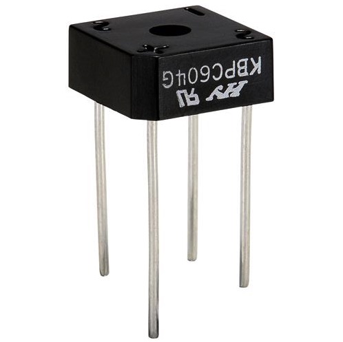
- Bridge Rectifier
- 6-foot of hookup wire, 16 to 20 AWG.
Preferably in 4 colors. I photographed in red, orange, pink, black.
If you substitute colors, print out the schematic and other relavent pages and mark up the color changes.
This wire passes at most 0.5 Amp at 14.2 VDC
Jameco 18 gauge hookup wire
The Bridge rectifiers come from
Parts-Express and are 400V 6A Bridge Rectifier -- Part # 050-030
The resistors (I usually buy them in quantity and keep some in stock) come from
Parts-Express and are 47 Ohm 10W Resistor Wire Wound 5% Tolerance -- Part # 016-47
Schematic of the robust power supply
Note that the AC to DC supply should have 14.2v output in order to float the GelCel propertly.
Step by Step.
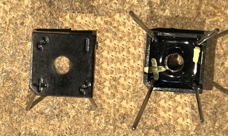
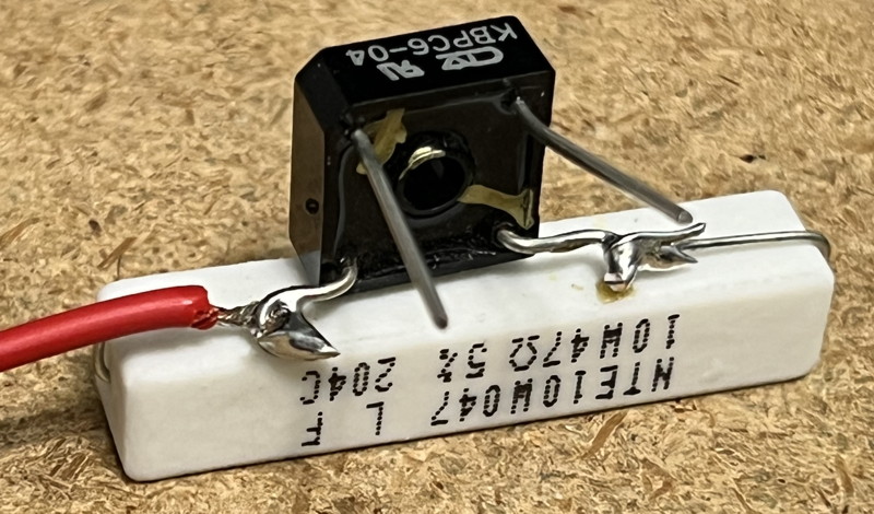
Turn the Bridge Rectifier on its back and mark the + and - corners of the part.
Note: Your project only needs one rectifier. The second is for show, here.
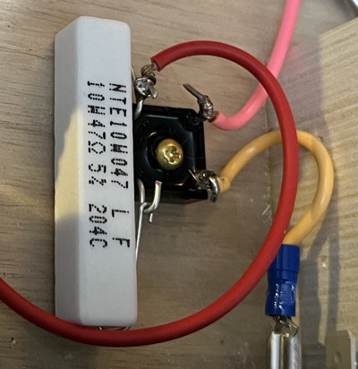
Spread wires on the resistor side of the rectifier
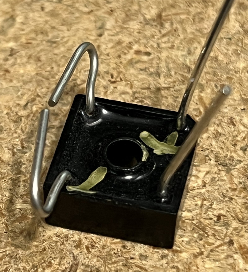
Wrap resistor wires around the rectifier wires
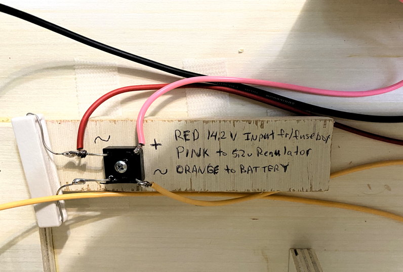
Add the 14.2 V power input wire.
Red is the color of choice for this.
Give yourself 6 inches or so.
Tie the wire around the resistor on the end
away from the - corner.
Solder the resistor wires to the rectifier and cut
Attach the other two wires. Pink to the + point (to regulator) and orange to the the ~ point opposite the resistor. Orange will provide charge to the battery, or current from the battery when the Meanwell is powered off.
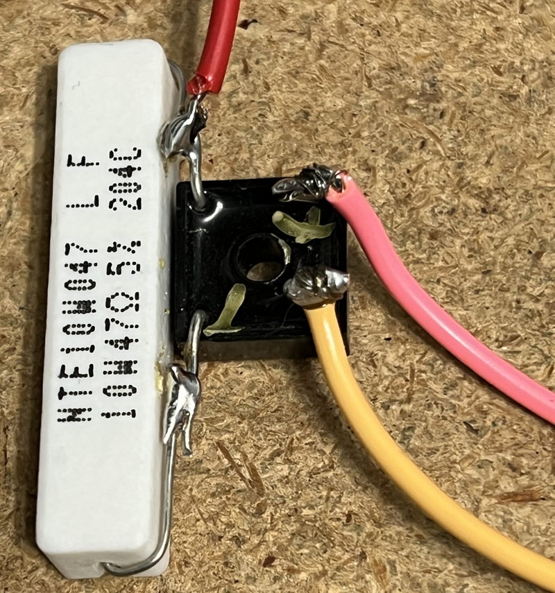
Here's another version of the same circuit I did when prototyping the project.