|
The TNC-PI is discontinued.
Support for TNC-PI is no longer expected to work on Raspberry PIs set up for TARPNs.
The TARPN project created the NinoTNC as a replacement for the TNC-PI.
NinoTNC is easier to build (as a kit), more powerful, easier to configure, easier to operate.
I'm leaving these TNC-PI pages intact, but the tools and commands referenced here only exist because they didn't get in the way, much.
Some elements will disappear from the TARPN tools over the next several years.
Please check out the NinoTNC at TARPN hardware projects documentation.
|
TNC-PI General Info
|
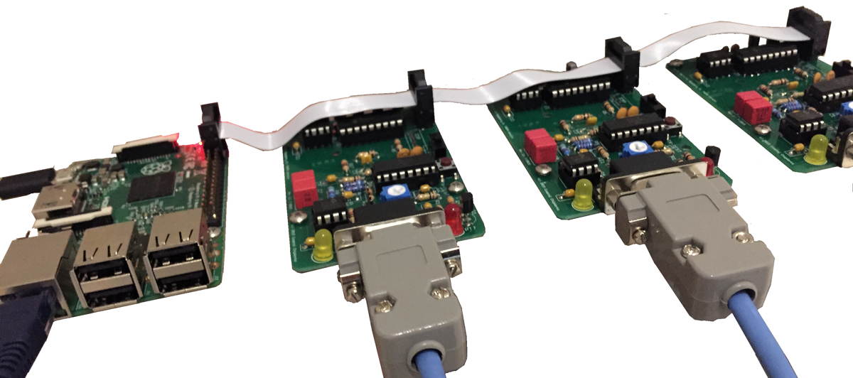
Until the NinoTNC project bore fruit in early 2020, the easiest, and nearly the cheapest, solution for a packet radio TNC, and most popular in our group, was a card made for the Raspberry PI called TNC-PI.
TNC-PI was a variation on the TNC-X made since 2004 by Coastal Chipworks.
Firmware for the TNC-X open source and is written by John W2FS.
TNC-X uses USB to connect to a host computer.
The TNC-PI was specifically designed to communicate to the Raspberry PI via its expansion header.
The TNC-X firmware from W2FS was modified by John, G8BPQ, to support the Raspberry PI's I2C bus, allowing multiple TNC-PI to be attached with a single ribbon, to the same Raspberry PI.
|
The TNC-PI was sold as a kit by Coastal Chipworks.
We sold them from our TNC-PI Kit Ordering and Assembly page.
They cost $43 plus shipping.
|
Key features of TNC-PI
|
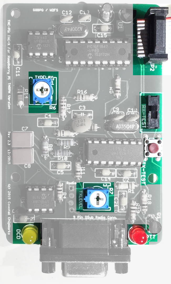
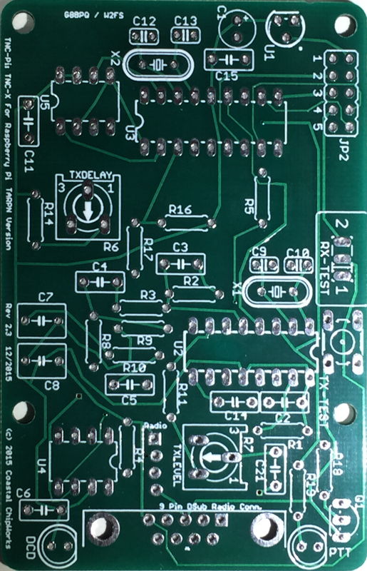
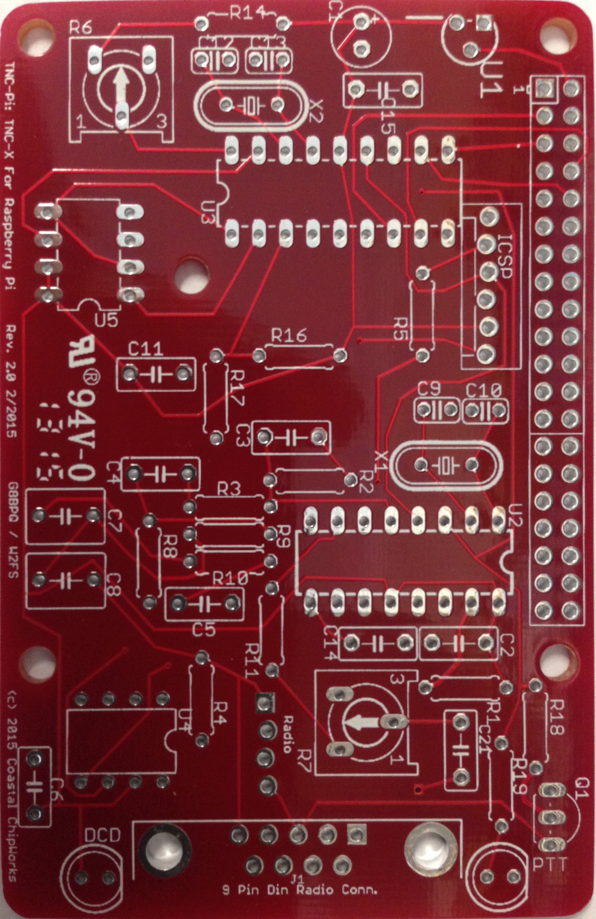
The DE-9 connector at the bottom of the photo is used to connect to the radio.
This connector has the same pin-out as the Kantronics KPC-3.
Lower in this web page there is an oblique (3d) image of the connector showing the pin-out.
The TNC-PI talks to the computer via the 2 x 5 header and ribbon cable shown in the upper right.
Other variants of the TNC-PI have 2x13 or 2x20 connectors.
For these boards, only the 10 pins closest to the top of the pictures (2 rows of 5) are used in communications with the computer.
The red and yellow LEDs are TX and DCD.
TX shows when the TNC-PI asserts PTT causing the radio to transmit, and DCD shows when the TNC is hearing both modem tones from the receiver.
R7 is the TXLEVEL (transmit audio level) control.
Adjusting R7 TXLEVEL affects the audio level generated by the TNC into the transmitter.
R7's setting needs to be checked each time a new radio is attached to the TNC.
See TNC+radio adjust and test for details.
R6 TXDELAY adjusts how long the TNC must wait after asserting PTT (TX) before the radio is ready for data.
On the right side middle of the board are a slide switch and a button.
The button is a PTT switch and while the button is held, forces the radio into transmit for testing purposes.
Note that the red LED does not illuminate when the button is pushed as the button just shorts across the DE9 connector.
The LED is driven by the circuit before the PTT transistor.
The slide switch causes the received audio to be copied to pin 7 of the 2x5 header.
This may be used by an audio monitor installed on the ribbon cable.
Only one TNC-PI in the node may have its switch thrown to copy at one time.
To copy audio into the ribbon cable, throw the switch toward the ribbon cable.
The default not-copy condition is slide towards the button.
|
|
Negatives of the TNC-PI
- Sold as a kit
- RF sensitive
- Only useful with Raspberry PI
The RF sensitivity issue comes up when using the TNC-PI near the antenna systems.
We've run into this problem with HTs located within a couple of feet of the computer/TNC-PI.
It has also been seen when using J-Pole antennas and 25 watt or higher power transmitters, and with home-brew yagi antennas lacking a gamma or T-match.
High-RF commercial locations where there are kilowatt broadcast transmitters or paging transmitters could cause a big problem.
Note: As of this writing I don't have much experience with the TNC-PI in commercial environments.
Please send me email via my QRZ page address!
RF sensitivity is usually
not a problem in residential environments when using well designed ground plane and yagi antennas except when the TNC-PI and Raspberry PI are located at the same level in the facility as the antenna.
Running a magnet mount on the porch on the other side of the wall from the TNC-PI could be a problem.
Setting the TNC-PI up with an HT mounted right next to it could also be a problem.
The symptom to be noticed would be that the transmitted audio from the TNC-PI would be of the wrong pitch.
You could demonstrate the problem by keying a 440 HT (on a different frequency from your link) right next to the TNC-PI while it is sending packets while you are listening to your link using a separate radio.
Solutions include relocating the antennas, different antenna choices, or using ferrite cores on signals going into the TNC-PI.
Because the TNC-PI has very little heat output, it would also be possible to shield the TNC-PI and use feed through capacitors for the seven signals passing in and out of the TNC-PI.
That doesn't sound like any fun, however.
The required signals are
radio: PTT, TxAudio, SpeakerAudio,
and Raspberry PI: I2C-SDA, I2C-DAT, Vcc5V, MonitorAudio(pin 7 of ribbon).
TNC-PI models
The original design of the TNC-PI was a stackable card that fit over the top of the Raspberry PI.
Most purchasers of the TNC-PI buy one unit and use it in this way, usually for APRS.
Our application, where we purchase several for the same system, is uncommon but not unique.
In our application, where there is likely to be more than one TNC-PI, the stacking of the TNC-PIs is not desirable.
There are 3 models of the board but at least 8 versions.
The most obvious difference between the models is the interface header which connects between the TNC-PI and the Raspberry PI, or connects multiple TNC-PI with a Raspberry PI.
The header versions are 10-pin, 26-pin, 40-pin.
Other differences:
- There is a mounting hole pattern difference such that the 26-pin version cannot be interchanged with the other two models.
The 10 and 40 pin units use the same outer 4 mounting holes.
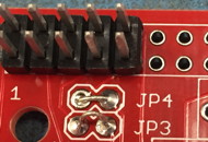
- The 26 and 40 pin units have a 6 pin debug header for use with an emulator for firmware development.
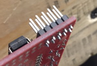
- The 26 and 40 pin units come with a pass-through header which which is soldered from the top, and which, according to the instructions, must be meticulously spaced half a millimeter from all the way down in order to prevent bumping into the USB connector on the Pi.
This header permits stacking of the boards.
- The 26 and 40 pin units, and modern 10-pin units, have an extra potentiometer hooked to an AtoD port which can be used to adjust TXDELAY.
In the 26-pin and 40-pin units the TXDELAY pot is marked R6 and is totally obscured if a ribbon cable is used to connect the TNCs together.
If the TNC-PI are stacked, both potentiometers are obscured.
- The 10 pin unit
- comes with an easier solder-from-the-bottom 10 pin header,
- has larger space around the mounting holes,
- has heavier signal traces,
- a push button for PTT, and
- a slide switch for linking the audio to one of the interface header pins.
- R6 is marked TXDELAY and is not obscured by the ribbon cable.
- R7 is marked TXLEVEL.
- It is sold through a link on the TNC-PI Kit Ordering and Assembly page.
All three models may be assembled with the 10 pin header for ribbon cable connection.
Multiple versions of TNC-PI
Below I describe the 3 TNC-PI circuit boards which are in current production.
For more details, see
Out Of Production TNC-PI.
V1.2 Apr2015
- JP7 (top middle) must be shorted to provide power to the board
- 2x13 Header
- R6 provides TxDelay control for this TNC but this control is covered if boards are stacked or if ribbon cable is used.
- NOTE: screw holes have insufficient keep-outs.
Use insulated spacers.
|
V2.0 Feb2015
- JP7 removed
- 2x20 Header
- R6 provides TxDelay control for this TNC but this control is covered if boards are stacked or if ribbon cable is used.
|
TARPN v2.3 Dec2015
- JP7, ICSP jumper/connector positions have been removed.
- 2x5 Header
- R6 is moved to a new location to be clear of the ribbon cable
- Adds PTT button and Audio copy-to-ribbon switch
- Improved silk-screen labels
- Center mounting hole removed
- Keep-out area around each of the holes is improved to support metal 1/4 inch hex spacers
- Thanks to John W2FS for doing these modifications for us.
|
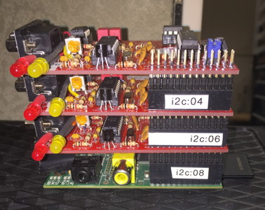
Using the TNC-PI in a stacked configuration
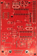
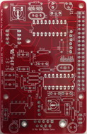
The red-board TNC-PI was intended to be stacked on top of a Raspberry PI.
The 26 and 40 pin versions have pass-thru connectors enabling multi-level stacking but only if the header is installed with a small gap between the header below the board and the PCB (else the spacer hardware is too long and there isn't enough room for the Raspberry PI USB connectors).
However, the board is difficult to operate and inspect in a multi-port node when stacked.
Method #1: Point LEDs and pots to the right
The good news with this is - the big header is exposed on top of the top TNC and now a non-TNC board can be part of the stack in case some accessory presents itself to the project.
So far we don't have such an accessory but who knows?
-
The assembled unit is relatively small.
The bad news with this is
- Soldering the through-connector is difficult
- The through-connector needs to be spaced manually to get the stacking spacing right else the USB connector shorts the bottom board and the screw spacers are too high.
- The boards are not rigidly mounted.
They tend to flop around a bit, or if screws are used, are mechanically stressed.
This doesn't portend a long life.
-
The boards are not individually accessible and the stack must be disassembled, leading to even more stress, to swap out or observe one of the middle cards.
-
The boards must be modified by hand, in ways the parts were not designed for, in order to attain even this level of accessibility.
-
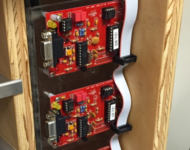
During assembly the two LEDs and potentiometer R7 are made to face sideways to the PC card so they are accessible and visible during operation.
|
|
If the boards are not assembled with the LED and R7 potentiometers modded to go out the side, you can't see the PTT and/or DCD lights, and you can't adjust the TXLEVEL without disassembling the stack (with the Raspberry PI powered down).
Method #2: Use IDCs and ribbon cable
During assembly, the 2x13 or 2x20 pass-thru header is left out and instead we substitute a 2x5 top-mounted header.
Ribbon cables made using insulation displacement connectors (IDC) and 10-conductor wire are used to connect the TNCs and Raspberry PI.
2x5-position IDC ribbon cables for a 4-port node cost about $6 to make and the only tools needed are a pair of pliers and diagonal cutters.
- All adjustments are available, the LEDs are very visible, and the versatility of placement of the TNC is very handy.
- The 2x5 connector is much easier to solder than the 2x13 pass-thru header.
- Solid mounting to nylon spacers is very nice.
- TNC-in-the-middle is removable without crashing the Raspberry Pi.
- The TNCs may be mounted such that the relationship between a TNC and its radio is visibly obvious.
Ribbon cables appear to be ok even up to 5 feet or more but this may depend on the RF environment.
I would keep them as short as convenient and consider this a source of problem if RF related issues develop.
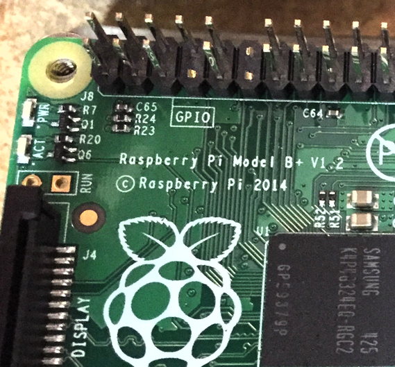
Note that if you using the 10 pin ribbon cable and 2x5 connectors, you will have to clip pins 11 and 12 on the Raspberry PI.
Pin 7 gets clipped so the Raspberry PI doesn't mollest the monitor audio used by the audio monitor.
Modify the Raspberry PI as shown to clear the ribbon connector and remove the chance of shorting TNC-PI receive audio to the Raspberry PI.
The pins you are removing are general purpose I/O pins which aren't needed for this project.
|
|
Don't panic about wrecking the future usability of the Raspberry PI.
It is a $40 computer which gets out-dated after only a year and costs about the same as a TNC.
If you choose to use a ribbon cable as described, the TNC models can be a mix of different models.
Sold as a Kit:
It takes a little over an hour to assemble a TNC-PI for the first time. Less time with experience.
Ordering and Assembly Instructions:
I made a web page with assembly instructions. I have also included a shortcut for ordering the boards and visual assembly instructions.
TNC-PI Ordering and Assembly
IDC connectors are available from ShowMeCables for 38 cents each or from SparkFun for 50 cents a piece.
Ribbon cable is available from SparkFun in a 3 foot length for 95 cents.
If you are in the Raleigh area, I have a cable, connectors, and
crimping skillz to spare for packet radio node projects.
--KA2DEW
Connector wiring
Modem chip specification
MX614P pdf
Additional Notes:
The TNC-PI has two potentiometers, R6 and R7.
R6 is an input to the A-to-D converter and can be used to set TXDELAY.
R7 adjusts the transmit audio level.
R6 in the stackable variants of the TNC-PI was in a location blocked by stacked boards or blocked by the ribbon cable.
It was deleted in the V2.1 TARPN version because we had been setting it in the I2C registers manually.
R6 was restored in later V2 versions because we decided that the original designers were correct and R6 is a wonderful way to set TXDELAY.
Also we were having weird problems with the TXDELAY value getting nuked.
R6 has a feature beyond setting TXDELAY.
If R6 is set to 0, the TNC-PI will trash its NVregisters when it boots, and then will get stuck in that mode until R6 is set higher than 0.
The Coastal Chipworks assembly instructions and web page for the stackable TNC-PI versions is here: TNC-X/TNC-PI
Schematic for the 26-pin version of the TNC-PI is here: tnc_pi_26pin_schematic.pdf
Schematic for the 10-pin TARPN TNC-PI v2.3 is here: schematic.jpg
Debugging PTT
This is text I wrote answering an email question.
Eventually I'll create a separate debugging-TNC-PI page
PTT doesn't work - what do I check?
Use the command
tarpn i2c-set # 15 3, where # is your TNC-PI's I2C address.
That will cause the TNC-PI to key up for about 10 seconds and send the two modem tones, high, then low.
The RED LED should illuminate while this is going on.
The only transistor on the TNC-PI, is Q1 which is the PTT switch.
Beware that the regulator and the PTT transistor have the same case.
Q1 is near the 9-pin D-shell socket.
The regulator is at the other end of the board from the D-shell socket.
The Microchip PIC CPU drives the transmit push-to-talk signal out pin 6 at 3.3v during transmit.
Ground during receive. The PTT signal goes through R18 and into the base of Q1.
At the same time the CPU drives pin 6 through resistor R19 to the red LED.
Look with a voltmeter on the CPU side of R19 or R18, or on pin 6 of the CPU and you should see a 3.3v high only during transmit.
On a red TNC-PI, R18 is in between the transistor and the 26 or 40 pin stacking-connector.
I measured R18’s pin on the stacking connector end of the resistor and see it go from 0 at idle to 3.3v during transmit.
The other side of the resistor goes to .66 volts. Is that the voltage drop across the transistor?
I presume so.
If you power off and unplug the CPU U3, then power the TNC back up, you can assert PTT by putting 3.3v on pin 6 of socket U3.
If the notch in the U3 socket is up and the expansion/stacking connector is down, then pin 6 is the 6th pin down on the left of the socket.
Pin 14, (5th pin down on the right side) will have VCC, 3.3v.
You can put a solid conductor wire between pin 14 and pin 6 and cause the PTT go fire indefinitely if you need to check this out.
I’m thinking that if this doesn’t work you should check the soldering around U3, Q1 transistor, R18 and R19 and the D-shell socket.
Many or all transmissions by my TNC-PI are garbled and cannot be decoded
The TNC-PI is RF sensitive, especially to UHF energy.
When RF is present at the TNC-PI, the first effect is that the TNC-PI transmitted tones will not be on frequency, causing the packets to be non-decodable at the other end of the link.
Make sure the antennas are located such that the TNC-PIs are not in the pattern of the antenna.
If the antenna is a vertical omni, the TNC-PIs should be below the RF radiation plane of the antenna.
If the antenna is a beam, don't point it at the TNC-PI.
Don't use unbalanced antennas or tricky antennas.
An unbalanced antenna would be a dipole or yagi fed without a
match.
Tricky antennas include J-poles or end-fed (fake ground) antennas.
If you are still having a problem with this, try wrapping the ribbon cable through a ferrite core and separately wrap the microphone cable through a ferrite core.
Note that wrapping each wire through its core more than once increases the RF cancellation effectiveness dramatically.
