Monitor RX Audio
This page discusses an easy to build audio amp assembly to allow the node operator to selectively listen to each of the radios hooked to a TNC-PI in the packet node.
An off-the-shelf cheap audio amp board is attached to the ribbon cable.
Why?
The receive audio is adjusted by the volume control on the transceiver.
It is fed from the radio into the DE9 connector on the TNC–PI.
If the receiver is not working, or if the audio connector is disconnected or shorted, or if the transmitting station is weak, or distorted, then the packet link is not going to function.
Often some aspect of the received signal is marginal but the TNC–PI and the node can't tell you how or why.
The human ear can discern many problems.
How?
Ordinarily the receiver audio is not available because it is tied directly into the TNC.
Modern TNC-PIs have a switch to monitor the audio.
What this does is steer the received audio to pin·7 of the ribbon cable to be picked off by an audio amp hooked to the ribbon cable.
The audio amplifier needs to be a high–impedance–input device so it does not impact the quality of the audio fed from the receiver to the TNC modem.
We've had good luck with a unit called
LM386 DC 5V~12V Mini Audio Amplifier Board Amp Module and available on eBay for around a dollar or on Amazon for $7.
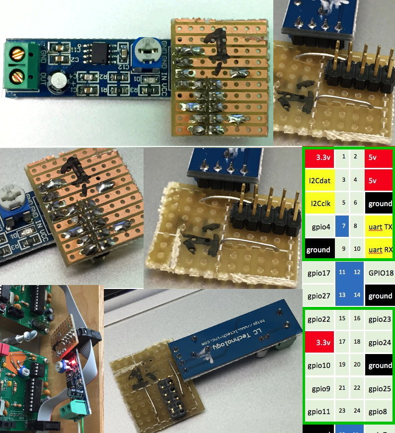
About the images
The end of the 10–pin connector marked
"1" corresponds with pin·1 and 2 on the Raspberry PI header.
The table on the right is a pictorial about that header.
On the Raspberry PI, pin·7 is clipped off so it does not connect to the ribbon cable.
Pin·7 is used by the TNC–PI and the RX audio is delivered to pin·7 if the slide switch on the TNC–PI is closed, i.e. toward the ribbon cable.
The node must be configured so no more than one switch is closed at a time.
Keep in mind when looking at the solder side of the proto board that pi pin·2 will be on the left!
The assembly consists of a 2x5 header, like the one used on the TNC‑PI.
If ordering a header, search for "2.54mm 40x2 Pin header".
The header is available from many sources including Amazon, though in this case Amazon is 10x or more overpriced.
The headers come in a 20 or 40–pin long form and can be cut down to make multiple 2x5 headers.
I also used a cut piece of stripboard prototyping board like that available from
Amazon here.
The wire I used was a clipping from a resistor after building the TNC–PI kits.
It just needs to be solid wire thin enough to be used on the strip board.
It can be very thin wire.
The connections made from the audio board on the 4–pin end are ground, (audio IN), VCC.
I placed the audio board so the VCC lines up perfectly with pin·2 of the ribbon cable connector.
The volume pot on the pictured board is backwards from a conventional volume control.
Pin·7 is wired to the IN pin on the audio module.
Pin·6 is wired to the GND pin on the audio module.
The ground connection on the TNC–PI is through pin·6, and pin·9 is left floating.
On the Raspberry PI pin·6 is connected to pin·9, but use pin·6 anyway.
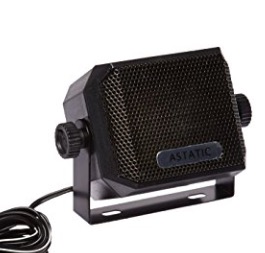
I prefer a speaker in a stand-alone housing.
They are easy to mount and keep out of trouble.
I found one on Amazon for under $10 called
Astatic 302-VS4 CB speaker.
This speaker has flat surfaces which are easy to Velcro or attach with double–sided tape.
I cut the connector off the speaker's wire and tinned the two leads with a soldering iron and then screwed the into the audio board's screw terminal block.
Note: Unscrew the terminal block, then insert a wire, then tighten the block.
The wires to the CB speaker are unlikely to be polarized unless the speaker chassis is metal.
Don't wreck the board by over tightening.
|
|
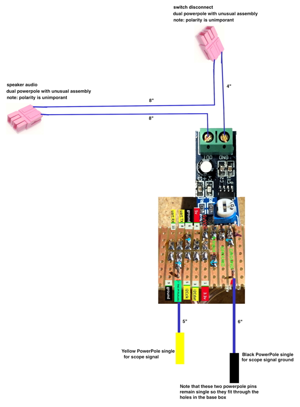
Connecting the Oscilloscope
The audio monitor card is a perfect place to grab audio to the DSO 138 oscilloscope.
Assemble the audio connections using a robust hook up wire which will not fall apart through repetitive movements.
The color coding on the wire is not important but the color selection for the powerpoles should be respected.
This way the audio assemblies may be interchangeable.
Click to embiggen
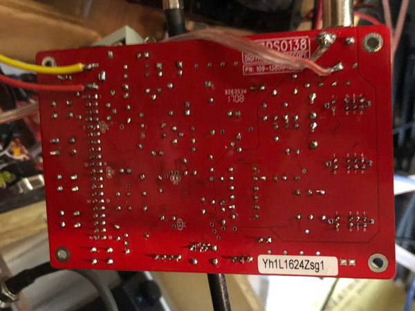
Back of the DSO138 Oscilloscope
See also Using an Oscilloscope for measuring Rx Audio Level to TNC-PI.
Note the red(9v) and yellow(ground) signals.
These colors are arbitrary.
Some power supplies have hard wired colors including using the yellow as 9V supply output!
The 9V power input to the DSO 138 is the lower of the two pins, which is red in this case.
The GND pin on that connector is the upper of the two pins.
That pin is both signal and chassis ground for the scope.
The red and clear wires come directly from the power pole connections to the audio board.
The yellow powerpole pin goes to where the red-striped side of the zip cord is shown on the back of the scope.
The black powerpole pin goes to where the clear side of the zip cord is shown.
Yellow and red power signals are soldered to the bottom of the bullet coaxial power connector.
Make sure you use an ohmmeter to do continuity tests to makes sure you have your wires attached correctly.