Using an Oscilloscope for measuring Rx Audio Level to TNC-PI
See also TNC and Radio Adjust and Test for photo of the TNC-PI board showing pins to directly measure the audio level using a bench oscilloscope.
This page is obsolete, as the NinoTNC is much easier to operate that the TNC-PI.
To operate a TNC-PI, you really wanted a scope and this one was barely good enough to perform that task.
If you do need a scope to debug something, including the NinoTNC, you'll probably want a nicer one and the JYE's only redeaming feature is low cost.
Even one of the early 1980s Tektronics lab scopes left in the trash after the hamfest is better than this one.
We did manage to get this working at most of the NCPACKET nodes, but it took a lot of T.L.C. to make that happen.
See if this link works: Adafruit product#468
In 2018 we started including an oscilloscope as part of the standard equipment for a TARPN node.
The
JYE DSO138 scope is available on Amazon for under $30 as a fully assembled item.
Beware that the kit is a bit difficult to build so make sure you get the fully-assembled unit.
You can find these assemble DSO138 scopes on Amazon for about $25 with free shipping.
When shopping for the DSO138 kit, you may have to read between the lines to decide what scope to buy.
If using a stackable mod-box cabinet made by Mark KM4JRH, Don N2IRZ, or Fin NC4FG, you don't need the Acrylic case.
You just want a DSO138 where all of the parts are soldered down.
Some of the
kits are sold with the words "welded SMD" which means that the surface mount devices have been soldered down.
All of the units are sold that way.
What you are interested in is all the rest of the parts to be soldered appropriately.
One of the nastyier adverts has pictures showing the scope but they are
only delivering the Acrylic case, i.e. case but no scope.
The big problem is that the venders of the scope never stay constant.
I believe this is because they are ripping off the original manufacturer of the scope.
I would recommend buying it from the original designer except that I can't see how to buy the
assembled unit at any price using PayPal, and the vendors he chooses (do they change periodically or am I seeing things?) are too fishy to want to give a credit card to.
Furthermore, in the forum on JYE's website, user jye1 says that vendors that are legitimate are not necessarily listed on the
good vendors list because they are not
direct suppliers.
JYE publishes a list of
bad vendors but the ones on Amazon aren't on the good or the bad list.
JYE also says that you can tell if the scope is a rip-off if it has a sticker with a proper serial number, but then JYE says you have to actually register with the JYE forum and ask if it is legit.
JYE says that if the sticker isn't there, then it is ok because it is old stock, but then 3 posts later JYE says that if the sticker is missing it is counterfit.
This is very bizarre.
To avoid all of this ligit or not question, consider
Adafruit's DSO Nano v3 for $140
So... I have bought about 15 of the DSO138 scopes, most of which have ended up in packet nodes.
This has been very good for link reliability because now at least the receive adjustment process is trivial.
The DSO138 runs on 9v.
Rather than hassle with wall-warts, the builders have been using a 12v to 9v regulator device found for about $4 on eBay.
We've been soldering the wires from the 9v supply to the back of the DSO138 and also soldering the signal lead to the back of the DSO138 as well.
The signal lead is brought over from pin 7 of the TNC-PI ribbon cable.
Everybody who has the full time scope as part of the node, has also used an op-amp audio board and this makes a great location to connect the scope.
See also
Monitor RX Audio where at the bottom of the page the back of the scope is presented.
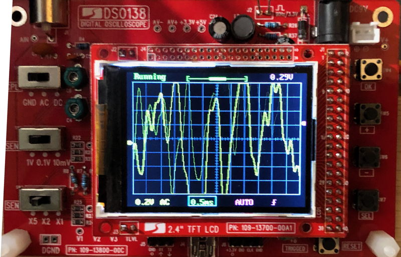
The DSO138 scope can be set up to show volts at 0.2V per division, with AC coupling.
Set the 3 switches to center positions.
Using the buttons on the right, select 0.5mS sweep rate.
Each receiver in your packet node should be receiving packets whose high frequency tones are at least 0.6 volts peak to peak, or 3 graticules high.
The lower frequency tones should be no more than 1.2volts peak to peak, or 6 graticules high.
Ideally the two tones would be nearly the same voltage at about 4 graticules high.
Image 6667
On the DS138 oscilloscope, at a receiver showing nearly the same voltages for both tones, this is adaquate.
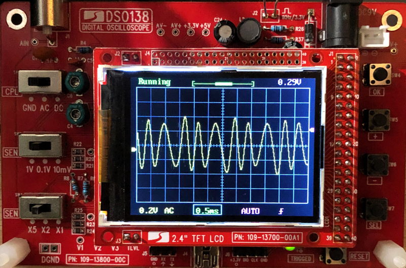
image 6665
In this image the voltage excursion is a little higher than above, but it still in the useable range.
Note that the two low tone is only 20% wider excursion than the high tone.
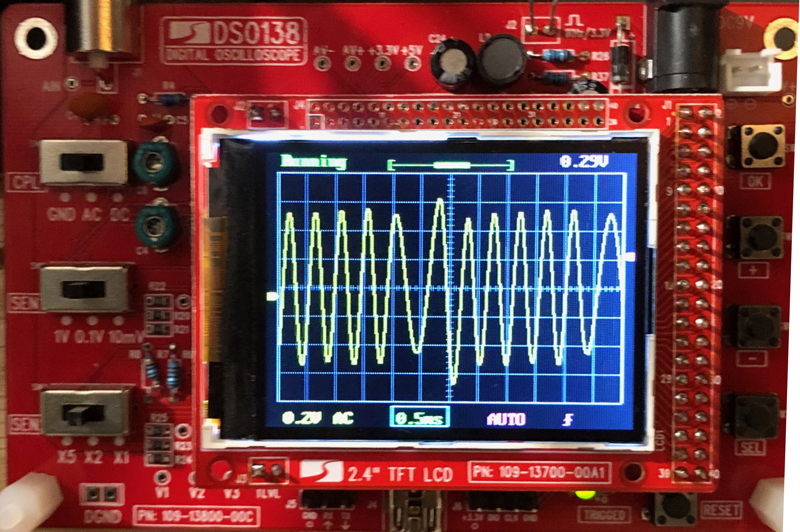
image 6666
Here's another with the tones nearly the same.
This one could be a tiny bit more volts.
Just turn up the volume a tiny bit.
That's a function of the transmitter on the other end, and our receiver.
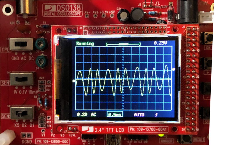
image 6654
This images shows packet receiption where the two different tones have very different voltage excursions.
THis is also ok since the lower frequency voltage is still within (or very close to) the 6 graticule's high limit.
If you have a chance to figure out whether it is the transmitter or receiver giving the wide difference between the two tones' voltages, do so and consider bringing in another radio.
It may be ok to have this skew of voltages if the received signal is very strong, i.e. full quieting, but I think this kind of thing would make a slightly noisy link get errors on the packets.
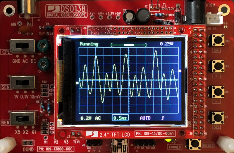
image 6670
This scope image is showing the squelch noise after the other end's transmission ended.
Squelch noise can be loud and that's ok.
We're only interested in measuring the received packet tones.