NinoTNC N9600A Operation
page modified October 28, 2025
Specifications may change without notice.
Do not use this device in any situation where the loss of life or property would be the result of the device misbehaving or failing.
If you go beyond this rule, you are self-certifying this device.
This device is built by hobbyists for a hobby project.
We do not certify that this design, or any particular unit, is sound.
Use it at your own risk.
|
For the most part, this document addresses the performance of Versions A2 and later
running the latest distributed firmware.
See
History page for firmware release history.
I welcome any more comments or instructions to go in this space.
Please volunteer whatever you have.
Send to the ninotnc email reflector.
Thanks!!!

Table Of Contents
- NinoTNC Readiness
- Third Party Manufacture of NinoTNC
- Application Operation
- Cabling
- Modes - Over-The-Air-Bits-Per-Second - AX.25 vs IL2Pc
- Performance of AX.25 vs IL2Pc
- Performance of 1200, 2400, 4800, 9600
- Performance of 300, 600 bits-per-second HF modes
- Board Revisions - Differences
- Board capabilities
- 9-pin D-sub DE9 for the A2, A3, A4 NinoTNCs -- 6-pin DIN for the V1-SMT NinoTNC
- Data radio vs Microphone radio
- LED Behavior
- LED Sweep on RESET
- LED Behavior on first start
- LED indicating test mode
- Unit ID mode
- Failed or Interrupted Bootload
- Receive
- Volume Level Requirements - Peak-to-Peak Tolerance
- DCD
- DCD at wrong bit-rate
- RXA scope loop
- AX.25 and IL2Pc Receive
- CRC Flicker - High Rx Volume Indication - Adjustment Helper
- CRC Latched - Uncorrectable Error in Received Packet
- Not Full Duplex
- USB - serial ports
- Serial Baud Setting
- MSWindows
- Linux and Unix
- Microchip MCP2221 Configuration Utility
- USB Port Identification
- Transmit
- TXDELAY Potentiometer
- TX-DEV and TX-TEST
- By-the-ear Method of TX-DEV adjustment
- SDR Method of TX-DEV adjustment
- Autonomous Transmit of Station ID and Mode (Beacon)
- Bootloading a new version of Firmware
- Bootlading Board Version Compatibility
- How the Bootloader Works
- Bootloading Failures
- Procedure
- Fixing a Bricked CPU
- Flashing to an Older Version
- Notes for using NinoTNC
- Baud Rate Selection for Your Host Interface
- NinoTNC baud/bit-rate Compatibility with Other TNCs
- TX-DELAY-control Delayed Effectiveness
- TEST-TX button
- TEST-TX in TARPN mode (CQBEEP-5)
- NinoTNC N9600A4 SIGNALS Switch: AC vs DC coupling
- IL2Pc vs AX.25 Selection
- KISS/Host Parameters: SLOTTIME and PPERSIST
- KISS/Host Parameters and note on TXDELAY
- Host Parameter: FRACK setting
- A2-Specific Instructions
- A3-Specific Instructions
- Data radio vs Microphone radio
- A3r1
- A3r2
- A3r3
- A4-Specific Instructions
- MODE Switch
- SIGNALS Switch
- V1-SMT-Specific Instructions
- 12-96 Slide Switch for Audio Input
- Six-Bit DIP Switch
- Transmit and Receive Audio Switches
- 9600 Baud Receive Eye Pattern
- USB Data Dump GETALL message
- G8BPQ Node Config
- 3d-Printed Enclosures
- NinoTNC-based Test Modes Bit-Error-Rate + Beacon
- Linktest test-packet-generation
- Bit Error Rate Transmit Mode:
- Bit Error Rate Receive Mode:
- tnc-tools Python Tools For Configuring and Querying NinoTNC
- n9600a-cmd.py
- kiss-listen.py
- kiss-ax25-ui.py
- kiss-ax25-ui-batch.py
1. NinoTNC readiness
The NinoTNC CPU is fully programmed with all the firmware you need to support the available modes at the time the CPU was shipped.
The NinoTNC is reconfigured by switches, jumpers and two potentiometers.
One of our product management mantras is that the operator can visually inspect the NinoTNC to discern the bit-rate, mode and TXdelay settings.
We also put the adjustables, LEDs and the test switch out front so that even with a box around the device, it can still be tuned up and checked out.
We are ever improving the LED diagnostic output and we've got a built-in loopback test so the owner/builder/operator can verify much of the functionality of the NinoTNC without external test equipment.
1-1. Third-Party Manufacture of NinoTNCs
We are happy to work with organizations that would like to work with us to manufacture the NinoTNC for Amateur Radio purposes.
Please see this web-page about the details, including materials we have made available:
Information about starting a new Third Party Manufacture of NinoTNC
See our Info, News and Ordering page for details on ordering in the USA, UK and EU.
2. Application Operation
Since this is a KISS TNC, it will be operated by an application that knows how to control a KISS TNC.
Except for hams running the TARPN installation and using the scripting and applications as provided for those installations, we are not supplying the application.
Except for the TARPN installations, the configuration of the application is out of scope, so far, for our instructions.
3. Cabling
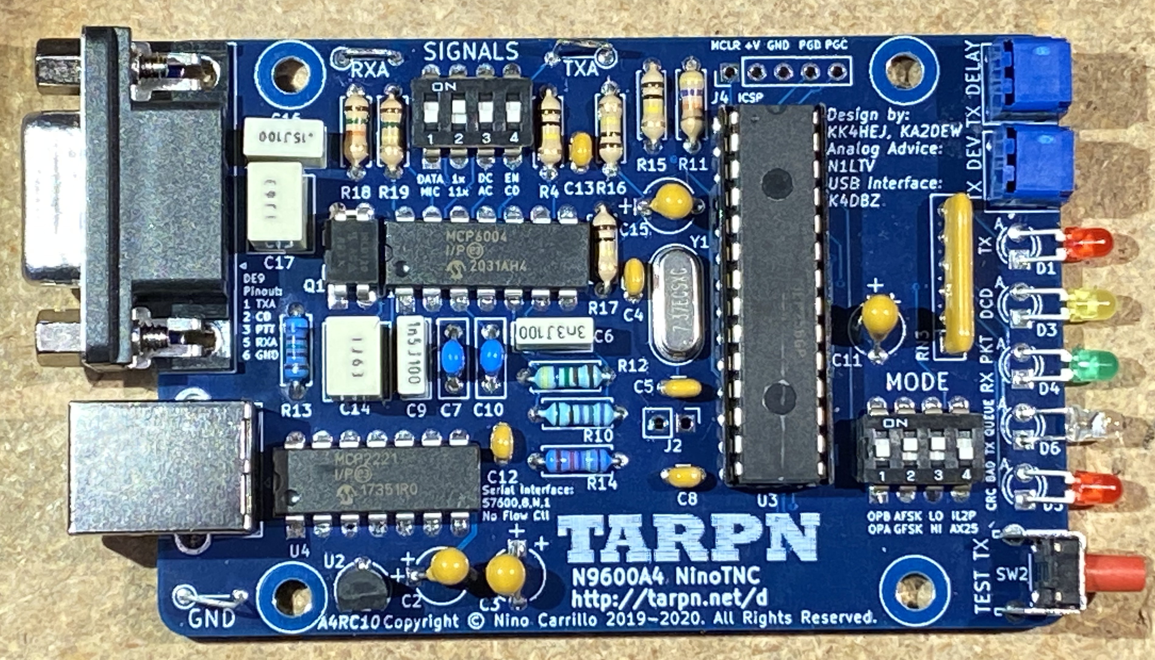
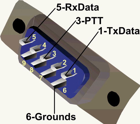
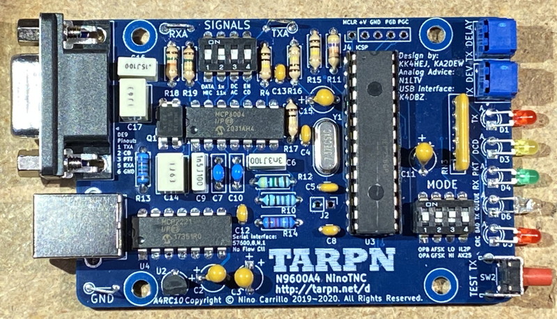
The kit NinoTNC has one radio port which is a D-sub 9 connector (correctly: DE9).
This is the same connector used by Kantronics since the mid-1980s and also used by Coastal Chipworks for their TNC-PI.
The fully assembled SMT NinoTNC has one radio port which is a 6-pin mini-DIN connector.
This is the connector used on Kenwood, Yeasu, Icom and other ham radios for packet radio use.
While the SMT NinoTNC has two receive audio inputs, 1200 and 9600, they are electrically equivalent, from the perspective of the NinoTNC, and there is a slide switch on the NinoTNC to decide which audio pin is active.
The ham radios presenting this connector will have separate audio paths for low-speed 1200 and high-speed 9600 received packet data.
The 9600 circuit in the radio is expected to have less audio processing and will be of a more flat frequency response than the 1200 circuit.
These drawings are of each connector from the perspective of the back of the plug you will be assembling to plug into the NinoTNC.

Some of the more common cables used in TARPN networks are described in
Radios and Wiring for Radios.
For store-bought cables, especially for ham radios, check out
Ham-Made-Parts [hammadeparts.com].
4. Modes - Over-The-Air-Baud - AX.25 vs IL2Pc
The NinoTNC has 15 modes.
Some are suitable for HF.
All can work on VHF.
3 modes are expected to be fully interoperable with other firmware TNCs.
These three are 300 AX.25, 1200 AX.25 Bell 202, and 9600 AX.25 G3RUH-like.
The NinoTNC and the KK4HEJ's firmware is the original work for creating/testing/deploying Improved Layer 2 Protocol, which is catching on with software TNCs and other hardware TNCs.
IL2P is only compatible with other IL2P stations.
The NinoTNC performs packet transmission and reception in 300, 600, 1200, 2400, 3600, 4800, 9600 and 19200 bits per second in IL2P and 300, 1200 and 9600 bits per second using legacy AX.25.
The NinoTNC A2 has dip-switch access to four mode-sets, depending on the firmware version.
See the A2 specific instructions, in this document, for details.
The NinoTNC A3 and NinoTNC A4 have a 4-switch "MODE" dip-switch providing access to all of the existing mode-sets.
The existing mode-sets for Firmware version 3.41 and 4.41 are:
| Common legacy compatibility modes |
| bps/modu | encoding | MODE
switch | Description |
| 300 AFSK | AX.25 | 1100 | HF packet 1600/1800 Hz tone FSK. Filtered for 500 Hz occupied bandwidth.
Used with SSB transceiver for HF packet with KAM or PK-232 stations. |
| 1200 AFSK | AX.25 | 0110 | 1980s FM packet - use for APRS and old-school TNCs |
| 9600 GFSK | AX.25 | 0000 | G3RUH AMSAT mode with discriminator/varactor connection or '9600' port - Kantronics KPC-9612, DRSI-9600, PacComm 9600 compatibility |
| |
| Latest SSB and FM modes - Improved Layer 2 Protocol with supplemental CRC.
These are intended to work on SSB sideband channels or with Mic/Speaker connections on FM transceivers. |
| bps/modu | encoding | MODE
switch | Description |
| 300 AFSK | IL2Pc | 1110 | 1600/1800 Hz tone FSK. Filtered for 500 Hz occupied bandwidth |
| 300 BPSK | IL2Pc | 1000 | Phase modulation of 1500 Hz tone. 300 symbols/sec. filtered for 500 Hz occupied bandwidth |
| 600 QPSK | IL2Pc | 1001 | Phase modulation of 1500 Hz tone. 300 symbols/sec. filtered for 500 Hz occupied bandwidth |
| 1200 BPSK | IL2Pc | 1010 | Phase modulation of 1500 Hz tone. 1200 symbols/sec. 2400 Hz OBW. |
| 2400 QPSK | IL2Pc | 1011 | Phase modulation of 1500 Hz tone. 1200 symbols/sec. 2400 Hz OBW. |
| |
| Best in class for narrow FM radio or Mic/Spkr - Improved Layer 2 Protocol with supplemental CRC.
This is intended to work on a 12.5Khz narrow FM transceiver, or a Mic/Speaker connections to an FM transceiver. |
| 3600 QPSK | IL2Pc | 0101 | Phase modulation of 1650 Hz tone. 1800 symbols/sec. 300-3000hz
Designed to pass through standard FM audio filter. |
| |
| Latest NinoTNC 4800 bits oer second, 9600 bits per second and 19200 bits per second modes, using a data port connection or discriminator/varactor connection to the radio innards. |
| bps/modu | encoding | MODE
switch | Description |
| 4800 GFSK | IL2Pc | 0100 | (10 khz occupied bandwidth) Improved Layer 2 Protocol with supplemental CRC |
| 9600 GFSK | IL2Pc | 0010 | (20 kHz occupied bandwidth) Improved Layer 2 Protocol with supplemental CRC |
| 9600 C4FSK | IL2Pc | 0011 | (10 khz occupied bandwidth) Only v3.41/v4.41 and later |
| 19.2K C4FSK | IL2Pc | 0001 | (20 kHz occupied bandwidth) Only v3.41/v4.41 and later |
| |
| In addition to the above tables, the NinoTNC has support for five modes which are to be dropped in future releases and which are compatable with early version IL2P TNCs.
There was an error in the IL2P spec and some bit errors can get through.
The new "IL2Pc" has an additional CRC step which fixes that problem.
Now the fix is in, and the old modes will go away to make room for new features/modes as those features become available.
The legacy IL2P modes are provided as a convenience for network users who want to upgrade but not orphan the neighbor running an older version of firmware. |
| |
| Early Gen IL2P modes - provided for compatibility with an earlier IL2P version (without supplemental CRC). |
| bps/modu | encoding | MODE
switch | Description |
| 300 AFSK | IL2P | 1101 | 1600/1800 Hz tone. FSK filtered for 500 Hz occupied bandwidth
pending deletion sometime after firmware version v3.39/v4.39 |
| 1200 AFSK | IL2Pc | 0111 | this is backward compatible with IL2P |
| |
As of firmware version 3.41 and 4.41, the NinoTNC mode selection may be made using a KISS command if the MODE switch is 1111.
G8BPQ format is KISS SETHW 6 # to select a mode and save it in EEROM, where # is the decimal value of the MODE switch selection.
Use the same command but add 16 to the #, to have the NinoTNC only temporarily set the new mode.
KISS SETHW 6 14 will set the NinoTNC to mode 1110 which is 300 AFSK and save it in EEROM.
KISS SETHW 6 30 will set the NinoTNC to mode 1110 which is 300 AFSK and NOT save it in EEROM.
RESET will bring the NinoTNC mode back to the last saved value.
The default setting, if no KISS SETHW command (with write to EEROM) has been performed since firmware FLASHing, is 0, i.e. 9600 GFSK AX.25.
1 means 0001.
|
| KISS SETHW | | 1111 | Enable KISS SETHW command to select operating mode |
4-1 Performance of AX.25 vs IL2P (IL2Pc)
IL2Pc is a forward error correction method, not compatible with AX.25 or FX.25.
The IL2Pc selection requires that all radios on the radio LAN conform to IL2Pc.
If that can be arranged, on VHF, a 4dB improvement on the required signal-to-noise ratio of the receiver used is realized.
This means that for any VHF/UHF radio set that can use the selected bits-per-second rate, the required quieting/signal-to-noise-ratio can be 4dB
worse and still have the packets decoded.
It is more efficient than FX.25, often as efficient as AX.25, but still providing forward error correction.
This means that between two IL2Pc-equipped TNCs, it is an easy choice to switch to IL2Pc because the packets are less susceptible to loss in noisy situations.
IL2Pc is described in the
Improved Layer 2 Protocol..
All of the selectable modes are configured by dip-switches.
4-2 Performance of 1200, 2400, 3600, 4800, 9600
The performance of the modems is depended on various factors including the modulation bandwidth of the radios, receive filters, and especially the signal path from the FM discriminator to the NinoTNC and NinoTNC to the modulator.
Some radios have an especially high fidelity signal path provided for each using a specially created/marked data connector.
On these radios, it is expected that 4800 baud and 9600 baud will be supported, as well as 1200 and 2400 baud.
The performance of the modem firmware in the NinoTNC is not consistent across all bit rates with respect to the quieting level of the FM signal.
Historically 1200 baud has always worked better than higher bit-rates, but some of the lore and history are biased because of the limited knowledge of the audio amp bypass techniques used for 9600 baud on FM transceivers.
The NinoTNC performs about the same at 1200 baud as 4800 baud on radios with a sufficiently idealized audio path.
2400 baud and 9600 baud are several dB worse than 1200 and 4800.
This means that the signal-to-noise-ratio at the receiver (related to the S-meter reading but not necessarily coordinated with signal strength) must be better for 2400 or 9600 baud to work well.
Most 25khz bandwidth voice radios can do 1200 and 2400 baud packet using NinoTNC by connecting through the Mic plug and speaker jack.
This includes ham radio FM/PM transceivers and most commercial 2-way radios manufactured for 25khz bandwidth.
In recent years, some countries' government communications directorates have made rules requiring 12.5Khz bandwidth for commercial FM services and that means modern FM transceivers sold to those markets may not be suitable for packet radio using NinoTNC or older packet radio TNCs.
The 3600 mode is new with version X.39 and is expected to work even on Mic/Spkr connected radios and on 12.5Khz radios!
Let's find out?
Recently the US's FCC agency made a rule change that permits SSB bandwidth audio (I think I understand this) for digital operation on some of the Amateur HF spectrum.
The NinoTNC is expected to be able to run 1200 BPSK and 2400 QPSK using 2400 Hz bandwidth on HF.
I'm not totally clear on this.
Please do your own research and get back to us.
Write to [email protected] with reports.
4.3 Performance of 300 and 600 baud HF modes
The three 300 and 600 baud HF modes have better signal-to-noise tolerance than the 300 baud AX.25 standard mode. Write to
[email protected] with reports.
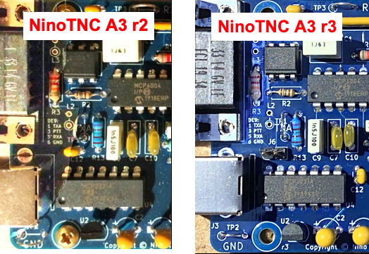
5. Board Revisions - Differences
There is a several-year history of the NinoTNC and there 5 different major versions of the NinoTNC out there still supported by the current generation of N9600A firmware.
The N9600A0 and A1 (August 2018 through January 2020) are no longer supported.
200 of the A2 (January 2020 through August 2020), 800 of the A3 (May 2020 through November 2020) and thousands of the A4 (December 2020 through at least 20237) are still supported.
In 2023 and 2024, Jason K4APR's RPC-Electronics-LLC SMT version of the NinoTNC was made and shipped.
Jason is making more once in a while.
See his website if you want one/some.
The N9600A4 PCB and CPU are shipping via ETSY with the remaining parts from Mouser.
The A4 is the cheaper choice but assembly is not included!
5-1. Board capabilities
All of the firmware available for the V1-SMT, A4 and A3 will also work on the A2.
The A2 only allows 4 MODE-settings whereas the V1-SMT, A3 and A4 can do 16 MODE-settings.
At this writing, the V1-SMT, A3 and A4 support seven different bit-rates, plus three base protocols, AX.25, IL2P and IL2Pc.
See board-specific paragraphs later in this document.
The A2 units had a daughter card for USB micro connection whereas the A3 and A4 units have a soldered-down USB-B (printer) socket and an on-board Microchip USB/serial chip.
The V1-SMT has an on-board FTDI surface mount interface chip.
The A3 and A4 have progressively more complicated and slightly improved TX and RX audio handling.
The V1-SMT is similar to the A4.
The A4 has a 4-bit SIGNAL switch permitting easy adjustment of receive and transmit gain.
The V1-SMT has 2 switches for audio control as part of its 6-bit DIP switch array.
The A4 has a selectable AC vs DC coupling, whereas the A2 and A3 were always AC coupled.
The V1-SMT is AC coupled only and otherwise has identical analog audio components.
5-2. D-sub DE-9 for the A2, A3, A4 NinoTNCs -- 6-pin DIN for the V1-SMT NinoTNC
The transmit audio and PTT signals on the A4 NinoTNC are the same as those provided on the V1-SMT NinoTNC.
Only the connector is different.
However, using the 6 pin DIN connector, there will be two different receive audio signals, identified as 1200 baud, and 9600 baud.
On ham radios having the 6-pin DIN connector, the receive audio is presented for low-speed with de-emphasis by the radio, and for high speed with "flat frequency response" audio.
There will be a menu option somewhere in the radio to select which of these two outputs is enabled.
The V1-SMT NinoTNC has a slide switch to connect the desired radio output to the NinoTNC's audio receive circuitry.
You'll want to make the same selection in the radio's menus as you make in the NinoTNC.
Switching the slide-swich in order to find the operative signal is just fine.
The NinoTNC is just fine with decoding 1200 baud packets on the 9600 wire and selection.
The different modes for 1200 and 9600 were provided by the radio manufactures in preparation for TNCs in the 1990s which were not as capable as the NinoTNC's DSP microprocessor.
5-3. Data radio vs Microphone radio
The microphone inputs, for the most part, are pretty sensitive and don't want a high voltage deviation to drive them.
Data radios usually want 1volt peak-to-peak drive, which is a bit louder than the microphone input radios.
The V1-5-SMT and A4 boards have a SIGNAL switch to select the drive level.
The switch is labelled DATA / MIC.
On the A4 board, if you are unable to get quality transmit performance, make sure you try the AC/DC selection.
Non-ham Data radios may require DC coupling.
A little history affecting the users of the A2 and A3 version kit NinoTNCs:
On the first of several publicly shipped versions of the NinoTNC, A2 and A3, the output level selection is made with a switch, jumper, a short, or soldering in a new resistor, depending on the version of PCB, with A2 boards requiring a resistor in the L2 slot to support a microphone radio.
The initial goal of the NinoTNC was to provide a low-cost 9600 baud option as a complement to the Coastal Chipworks TNC-PI.
When Coastal Chipworks announced they were discontinuing TNC production, TARPN moved to add 1200 capability to the NinoTNC and thus the NinoTNC A2 was born.
It wasn't until the A3 units started production that the TARPN NinoTNC project recognized that the drive level of 1200 baud radios would not be the same as 9600 baud radios and a special "hack" was added, both to the A2 instructions and the A3 boards.
This would allow running the output of the NinoTNC to the sensitive microphone input of a ham (or commercial 2-way) transceiver.
With the A2 boards a resistor must be added where none was provided for.
With the first release of the A3 boards, a resistor is provided for but a short must be added to optimally drive a data radio (that was a mistake).
With the second release (actually the 3rd version) of the A3 board, a 2 pin jumper/shunt position was provided to select data radio (shunt in place), or microphone input (shunt removed).
The A4 improves on that "hack" with a switch selectable drive level.
Later in this document are chapters specific to each of the production boards.
In addition, the History and Info web pages have details about individual revisions of the NinoTNC.
Each of the assembly pages has a schematic for the last version (most common version) of each major release.
See the history page for the complicated story of the A2 and A3 versions.
The A4 board has been very good.
6. LED behavior
In version 3.01 and later, and during NinoTNC normal run-mode, the five LEDs have this behavior, from left to right:
Red D5 CRC BAD
This LED has multiple functions.
The primary function is the
CRC was bad indication.
This rare event means that the NinoTNC received a complete packet which must contain a 16-bit Cyclic Redundancy Check number but the CRC calculated for the bits of the packet did not work out to the same number sent
as the CRC
in the packet.
The second function of the LED (added in version 2.7) is to flicker or illuminate when the audio coming into the NinoTNC from the radio exceeds the voltage range permitted for received packets.
This won't usually hurt the NinoTNC but it does indicate that the receive volume is set too high.
Using this indication, an operator can open the squelch on the receiver, then turn the volume control until the CRC LED illuminates or flickers, and then to turn it down until the flickers stop.
This will set the receive volume to an ideal level for the NinoTNC to perform the best decoding of the received packet.
Blue D6 Tx-Queue
Note: Was orange in the A2 and A3 versions. Blue in A4 and later versions.
This LED shows that one or more packets are stored in the NinoTNC, waiting to go out.
The NinoTNC is inhibited from transmitting by the detection of channel activity, or by timing.
This LED will flicker very briefly when KISS instructions are exchanged with the NinoTNC.
I haven't been able to see this so it must be very brief?
Note: A "stranger" feature was deleted in later versions of firmware.
See the History page.
Green D4 Rx Packet
This LED lights when a packet is received and decoded successfully.
It stays illuminated for 2 seconds, or until an undecodable packet arrives.
Yellow D3 DCD
Data Carrier Detect.
This LED lights when a bit clock is detectable in the received audio.
See Receive chapter.
Red D1 TX
This light is illuminated when the CPU drives the Push To Talk circuit on the NinoTNC.
If that circuit is working, the radio should be made to transmit.

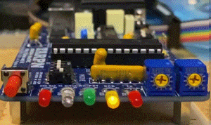
6-1. LED Sweep on RESET
The left-most four LEDs will sweep, as seen in the GIF movie above, when the NinoTNC CPU resets (i.e. the firmware starts over).
The NinoTNC Firmware program will make the TNC reset under several conditions including power-on and whenever the MODE switches are changed.
The NinoTNC Firmware program will repeat this sweep indefinitely if the MODE switch is set to an unspported or unspecified selection.
There is a safety feature in the firmware called
Watchdog which will reset the Firmware if some conditions occur which might be caused by a hung software routine in the TNC.
One of the tasks, kicked off by a timer in the TNC, checks to make sure that each of the critical functions (USB command processing, receive of a radio message) has occurred recently and if one of those functions has not, the TNC will do a reset.
A reset is not harmful to communications.
A freeze-up of a critical function would definitely be harmful.
The NinoTNC firmware was designed while keeping in mind that the TNC could be located in a remote location where rapid field service is not practical, so the developers were more interested in keeping the machine running than in the potential of a lost packet.
Preventing loss of traffic during a reset is also a high priority, second to having the TNC program not lock up.
One of the powerful behind-the-scenes parts of the NinoTNC program is the way the unit uses time.
The modem has a free-running high-speed clock that increments continuously.
When that clock gets within 1 day of running out of bits in which to count, the firmware starts looking for a perfect time to reset without interrupting communications.
Observers of the TNC over a long period will eventually see the LED sweep indicating a TNC reset.
This is normal and expected.
6-2. LED behavior on first start
When the NinoTNC is powered up for the very first time with a new CPU or a newly flashed/bootloaded CPU, the green/center/RX PKT LED will flicker for several seconds and then stop.
This is a feature.
The LED indicates that the bootloader program in the CPU is being overwritten with a new copy from the application that was programmed into the CPU.
This overwrite feature allows us to upgrade the bootloader program to improve capability or fix bugs.
6-3. LED indicating a test mode
There are several test modes, described in a later chapter, that may be triggered by pressing the TEST-TX button for 10 seconds.
Those test modes have LED operations of their own and they stick through power-up and reset-by-mode-switch.
Just press the TEST-TX button to clear these modes.
6-4. Unit ID mode
Old Feature - removed from the firmware in mid-2023
When applying power, or reset by mode-switch, the TNC will do the cylon sweep and then will flash the CRC red LED for about 3 seconds, possibly with 1, 2, or 3 other LEDs on solid.
After 3 seconds all of the LEDs go out.
This is Unit-ID mode which is a deprecated feature (scheduled to be removed in X.22) that makes it possible to set a SERNO in the NinoTNC's FLASH.
Reflashing or re-bootloading will clear this mode.
There isn't any way to clear this mode without flashing or bootloading.
The mode will affect only how the NinoTNC responds to the GETSERNO KISS command, the LED display at boot, and the contents of one of the records in the GETALL beacon and response.
In versions X.08 through X.21, the unit ID feature would be activated by powering up the NinoTNC while the Test-TX was depressed or shorted.
6-5. Failed or Interrupted Bootload
If a over-the-USB bootload has failed, but the CPU is not bricked, then when power is applied the 4 LEDs nearest the TEST-TX button will all illuminate solid.
Fix this by starting the bootloader FLASH command over again.
7. Receive
The NinoTNC has an automatic gain control built into its modem and is cable of handling a wide volume range.
The red LED near the TEST-TX button will illuminate if the receive volume is too high.
A switch in the Signals dip-switch will increase the receive gain by 11 times to support radios with extremely low RX levels (Kenwood TM-series Mic plug receive audio)
7-1. Volume Level Requirements - Peak-to-Peak Tolerance
The NinoTNC is comfortable with 3 V P-P and can do pretty good work down to around 0.3 V Peak-to-Peak.
This means that receive level adjustment (aka transceiver volume knob) is not so picky.
7-2. DCD
The NinoTNC has a very good Data Carrier Detect.
It prospers with open squelch.
The DCD is aggressive and can activate, or deactivate, in milliseconds.
The algorithm (it's done in the CPU) looks for coherancy between wave-form edges in the incoming signal, approximating the bit-time of the select bit-rate.
If data-carrier-detect is false, the NinoTNC will run a slot-time calculation and P-Persistance and may begin to transmit if there is a queued packet.
LED D5 - "Tx-Queued" - will indicate that there is a queued packet waiting to go out.
If the DCD detect is on, the NinoTNC is looking for an 8-bit sync phrase, signaling the start of an AX.25 frame, or a 24-bit sync phrase, signaling the start of an IL2Pc sync frame.
7-3. DCD at wrong bit-rate
The NinoTNC listens to one bit-rate only, i.e. 300 baud, 600 baud, 1200 baud, 2400 baud, 3600 baud, 4800 baud, or 9600 baud.
The NinoTNC listens only to the selected encoding mode and may detect, but will fail to decode, alternate encoding modes, i.e. IL2Pc vs AX.25.
If a 2400 baud packet comes in while the NinoTNC is configured for 1200 baud (switches) the TNC will completely ignore the 2400 baud packet.
The DCD detection is not designed to work on alternate bit-rates.
It is likely to falsely detect DCD on noise or from packets heard at the wrong bit-rates, for very short intervals, but in practice, a NinoTNC configured for 9600 could transmit right on top of even a strong 1200 baud packet.
DCD detect is based on the data-slicer’s guess about how well it has synchronized its regenerated bit clock to the zero crossings in the signal.
It needs to see 4 zero-crossings sequentially in sync with its regenerated clock, i.e. at the same bit-rate, to declare that it detects data.
The data slicer is constantly trying to synchronize its regenerated bit clock via a software PLL applied to the sliced receive audio.
When it sees 4 sequential zero-crossings in sync with its own regenerated clock, it turns on the LED, and sets an 80-bit timer to “coast” and hold DCD.
For each bit that goes by without sync, the 80-bit timer is decremented.
If a bit comes by that is at the appropriate
edge-time, the timer is set back to 80-bits.
When the timer hits zero, DCD is de-asserted and the LED is turned off.
7-4. RXA scope loop
The NinoTNC has an RXA scope loop to which you can hook an oscilloscope,
It is very informative to see some wave-forms passing through the radio and, with an oscilloscope, the RXA scope loop makes this trivial to do, even in a hurry.
You can also drive test audio directly into the RXA scope loop instead of having to wire up a DE9 connector for some experimental scenario.
One of the NinoTNC Kit Assembly tests is to connect the TXA loop to the RXA loop and see if the receiver is decoding the transmitter.
It is easy to connect another NinoTNC's transmit signal, i.e. TXA of #A to RXA of #B. Then TXA of #B can connect to RXA of #A.
Now you have a packet link on the bench, enabling exploration of the interaction of the software at two hosts, without tying up two radios.
7-5. AX.25 or IL2Pc Receive
If you set the NinoTNC to decode some bit rate, it will look for an incoming synchronization phrase (at that rate and with the implicit modem tones).
While synchronization phrases for AX.25 and IL2Pc are different, the NinoTNC will light its DCD LED and will avoid transmitting when either an AX.25 or IL2Pc packet of the same baud rate is heard on the channel.
The NinoTNC cannot be expected to respect transmitted packets in the wrong baud rate for the purposes of interference avoidance or lighting its DCD light.
7-6. CRC Flicker - High Rx Volume Indication - Adjustment helper
The CRC LED will flicker if the receive volume is too high.
With the squelch open (loud rushing noise), adjust the receive volume up until the CRC LED starts to flicker, and then bring it down until the flickering stops.
The NinoTNC is happy with you leaving the squelch open.
That will let the NinoTNC start working on the received packet sooner, since the squelch is already open.
7.7. CRC latched - Uncorrectable Error in Received Packet
The CRC LED will come on at the end of a received packet that was not delivered to the host because of errors (uncorrectable errors in the case of IL2Pc), but only if the failing packet is in the same protocol (AX.25 vs IL2P) as the most recent 'good' packet.
The CRC LED will stay lit for 2 seconds, controlled by a timer, regardless of other activity running simultaneously on the NinoTNC.
The NinoTNC will continue to perform transmit and receive, as called for, during these 2 seconds.
It is allowed behavior for the NinoTNC to display CRC error for a previous packet and RX PKT (green LED) for a following packet, at the same time.
7-8. Not Full Duplex
Except in the moments right after the TEST-TX button is released, the NinoTNC will either transmit or receive.
If the NinoTNC is decoding alternating bits it will light its DCD light and will refuse to transmit.
8. USB - Serial Ports
8-1. Serial Baud Setting
Even though the NinoTNC uses USB, there is still a serial baud configuration.
This describes the speed the USB-serial interface chip (FTDI or Microchip) uses to talk to the CPU on the NinoTNC.
The NinoTNC expects 57600 baud, 1 stop bit, no parity, for the USB/serial interface.
8-2. MSWindows
An MSWindows computer will assign COM port numbers.
AL0I did a PDF file on how to get the NinoTNC A3 and A4 boards working on MSWindows.
Linked here
An issue with using USB serial devices as TNCs, and which we must put up with, for now, is that the Linux or MSWIndows OS will enumerate the NinoTNCs at computer reset, and will then assign the USB/serial devices as they are ordered.
After another host computer reboot, the ordering is done again.
If a NinoTNC is removed after the enumeration is complete, the COM port numbers will not be reassigned until the next operating system reset.
Unplugging a TNC and then plugging the USB into a different port will result in the TNC reappearing, possibly as the same name.
But the name isn't sticky through reset!
Consequently, if the TNCs are assigned and some are replugged, and then later the host computer resets, the TNCs will show up with a new enumeration and the node will not function correctly.
The workaround for this behavior that we're using for now for Raspberry PI and Linux, is after your NinoTNCs are all plugged in, reset the host computer.
Now use the TNCs in the "final" enumeration.
On MSWindows, you can identify the USB/serial devices in the device manager.
Unplugging and replugging one of the NinoTNCs will allow you to see which COM unit is which NinoTNC.
8-3. Unix and Linux
An issue with using USB serial devices as TNCs, and which we must put up with, for now, is that the Linux will enumerate the NinoTNCs at computer reset, and will then assign the USB/serial devices as they are ordered.
After another host computer reboot, the ordering is done again.
If a NinoTNC is removed after the enumeration is complete, the
/dev names will not be reassigned until the next operating system reset.
Unplugging a TNC and then plugging the USB into a different port will result in the TNC reappearing, possibly at the same name.
But the name isn't sticky through reset!
Consequently, if the TNCs are assigned and some are replugged, and then later the host computer resets, the TNCs will show up with a new enumeration and the node will not function correctly.
A Linux host computer will assign
/dev/tty names in the order of what hardware/physical USB hub and socket it finds them on, with a separate sort for FTDI vs Microchip.
The USB devices which are FTDI (NinoTNC V1-SMT, A1 and A2) will show up in the device directory,
/dev, as
/dev/ttyUSB0, /dev/ttyUSB1, etc.
The USB devices which are Mocrochip MCP2221 (NinoTNC A3 and later) will show up in the device directory,
/dev, as
/dev/ttyACM0, /dev/ttyACM1, etc.
This Linux command will show what NinoTNC A3 and A4 units are plugged into your computer.
ls -l /dev | grep -e "ttyACM"
Also try:
lsusb | grep 04d8:00dd
8-4. Microchip MCP2221 Chip Configuration Utility
Microchip has a configuration utility that can change some of the parameters of the MCP2221 USB/serial interface chip.
This is the URL for the MCP2221 documentation.
MCP2221 USB 2.0 to I2C/UART Protocol Converter with GPIO
Scroll down to find a table with documents and the MCP2221 Utility.
The utility runs on MSWindows 10.
The utility enables turning on the serialization of the chip and also allows changing the "MCP2221 USB-I2C/UART Combo" text which shows up when the
lsusb command is used in linux.
8-5. USB Port Identification
Software writers of the various applications supporting more than one NinoTNC will need to discriminate between NinoTNCs so the appropriate traffic goes to each port and that it would be handy to have the ports figured out before networking routing begins (after power-up).
Some of the network software will allow text metadata to be applied to each port, and mapping the metadata to the correct port, at power-up, is tricky when using USB devices.
On all of the operating systems the USB ports are enumerated by the computer and the identification of the port is some alphanumeric text string.
The enumeration order can be difficult to discern when USB hubs are inserted, some of which may be inside the computer.
Moving a USB cable from one port to another can change the name assigned to the NinoTNC.
As far as I know, all of the text strings start with a standard several letters followed by an incrementing number that starts low and adds 1 for each USB port of like kind that is enumerated.
Keyboards, mice and audio peripherals are enumerated separately from each other and separately from the serial ports.
On most of the OSs there is a scheme for reading an identification from the USB device but access to that identification, both for setting and reading the identification can be troublesome.
The most obvious method for enumerating multiple NinoTNCs is to run a program that can talk to all of your NinoTNCs, and then issue a transmit command from that program to a specific port.
Note which port's transmit light goes on.
Add a label to the NinoTNC.
Do not change things.
The TARPN scripting associated with the G8BPQ node stack does something sneaky and tedious.
It gets a configuration file from the operator that details what neighbor callsigns are heard by the G8BPQ node.
When one of those callsigns shows up from one of the TNCs, it concludes that the particular TNC services that neighbor.
This process depends on the neighbor having transmissions to be received, and that the neighbor is configured appropriately for your NinoTNC.
9. Transmit
The NinoTNC has several transmit features including the TEST-TX button, IL2Pc transmit mode, and AX.25 transmit mode.
I'll try to describe all of this as this document evolves.
We'll also have to go into what KISS commands are implemented and how to use the NinoTNC-specific KISS commands.
The NinoTNC has a 2100-byte KISS input frame buffer to capture host-generated KISS messages.
That means the NinoTNC can afford to be given seven 256-byte host-transmit KISS packets, and store them all simultaneously.
If a KISS packet is pushed to the NinoTNC when there is not enough space to store an entire KISS frame in the selected transmit mode (i.e. 256 or 1023 bytes of the encoded packet), the host's KISS transmit frame will be silently ignored until its FEND end byte.
The NinoTNC can handle more than seven outgoing 256-byte frames in AX.25 mode because it has three transmit buffers that are filled with already encoded messages, so depending on the selected bit-rate and channel activity, it is possible to have 10 full-size outbound packet frames in the NinoTNC at once.
The NinoTNC does not artificially limit the number of outgoing packets stored in the from-host serial buffer.
Until the NinoTNC frees up an encoded-tx-ready-to-transmit buffer, it does not check to see what kind of KISS frame, or how long, has been received from the host, so you could buffer up quite a few short packets.
Each of the three encoded-tx buffers can hold one and only one transmit packet.
The IL2Pc mode can accept a 1023-byte transmit message in IL2Pc mode.
That means that if there are less than 1023 bytes free in the from-Host serial buffer, and the NinoTNC is in IL2Pc mode, the host's new outgoing KISS frame will be ignored.
Because of the encoded-transmit-buffers, mentioned above, it is possible for the NinoTNC to queue 5 full-length IL2Pc packets.
This will take some finesse because of KISS's specified silent-ignore in an overflow condition.
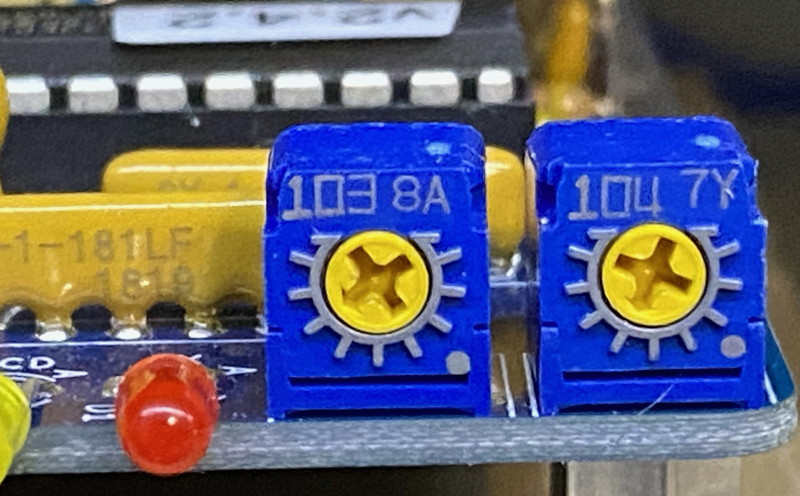
9-1. TXDELAY Potentiometer
The TXDELAY potentiometer adjusts the amount of time the TNC waits after keying PTT, and before sending the packet.
While waiting for that short delay to end, the TNC sends FLAGS or a 10101 pattern.
For the 1200 AX.25 mode, at the point of transmission, the data will be slightly more random-looking than that because there is a differential encoder that performs an expected bit randomization.
The packet receiver knows about this and does the translation automatically, so on the scope, it won't look quite so obvious.
In IL2Pc modes or G3RUH 9600 mode, the data is set as a 101010 pattern.
TX_DELAY setting will depend on the transmitter and receiver involved in the link. TX_DELAY adjusts the number of preamble words the TNC sends after keying the PTT line but before data appears in the bitstream.
This gives time for transmitter relays to switch, as well as AGC and AFC circuits to settle in the receiver. TX_DELAY is best set by trial and error, starting from a low setting.
The TX_DELAY response is exponential (the same amount of pot rotation at top scale results in much more preamble), and different for 1200 and 9600 modes.
In 1200 mode, the minimum pot setting gives 32 bits of preamble (27 milliseconds), and the maximum pot setting gives 1200 (1 second).
In 9600 mode, the minimum pot setting gives 112 bits of preamble (12 milliseconds), and the maximum setting gives 8656 bits (901 milliseconds).
In practice, most setups should work fine at about half-rotation on the pot.
If you want to optimize link throughput, you'll want to back off the TX_DELAY until the receiver stops receiving packets, then slowly increase until packets start coming through, then add a little more for a buffer.
Important note on the TXDELAY potentiometer operation with respect to the NinoTNC CPU/firmware:
The NinoTNC only reads the TXDELAY when it finishes sending a packet.
That means that an adjustment before a packet is sent will not be respected until the 2nd packet is to be sent.
Additionally, if the TXDELAY is set to minimum (maximum counter-clockwise), the NinoTNC will not use TXDELAY of 0, and will instead use the value sent by the host using the KISS TXDELAY command.
9-2. TX-DEV and TX-TEST
The NinoTNC has three output adjustments:
- The TX-DEV potentiometer adjusts the TNC transmit level (voltage/volume) over one of two voltage ranges.
- The output range control. This varies with the board version and can be a jumper or a switch.
The output range control sets the voltage range limits for the TX-DEV adjustment.
The ranges are Mic input level, or Data radio levels
- The third adjustment is TXDELAY, described above.
The TX-TEST/PTT pushbutton tells the CPU to key the radio’s PTT line, and generate a sine wave test tone.
The level this tone is generated with may be used to calibrate the TXLEV potentiometer.
The NinoTNC is designed to generate the appropriate sine wave level so if TXLEV during TX-TEST is appropriate for the other end’s receiver, so will the TXLEV be during a real packet.
When TX-TEST is depressed, the NinoTNC will generate a very audible sine wave.
Once TX-TEST is released, the NinoTNC waits for most of a second and then generates both a USB message and a transmitted packet.
The USB message shows up as a KISS packet-received frame with an information frame containing the text "
:Test Packet by USB".
The transmitted packet will be generated in the mode and the bit-rate selected by the switches.
The destination callsign used will be
ID.
The origin callsign used will be the last callsign your station used as
mycall to transmit a packet.
The callsign is stored in EEROM so it is recalled and used even after power is interrupted.
If no transmissions have been commanded over KISS, the callsign used will be
N9600A-3.
The NinoTNC will assert Push-To-Talk, and then send the packet, using the Tx-level and Tx-delay specified by the potentiometers.
At the same time the NinoTNC is transmitting the test message, it is also listening for that exact packet.
While the NinoTNC does not normally do full-duplex, in this case it can, because the transmitted packet is pre-engineered to permit this.
The received packet is also decoded and presented over the USB and will contain the text "
:Test Packet".
The LEDs on the NinoTNC will show that DCD comes on, and then a good RX packet (green) or a bad packet (red).
If the TX-TEST packet transmission uses the N9600A-3 callsign, and if it is looped back, the NinoTNC will show TX-queue, TX and DCD and then RX. Or, TX-queue, TX and DCD and then CRC BAD.
9-3. By-the-ear Method of TXDEV Adjustment
There are a few methods to help you set the TX_DEV pot appropriately.
For many applications, especially with AFSK 1200 mode, setting by ear will be good enough.
-
Attach the radio you'll be using for packet to a dummy load and the NinoTNC.
- Use an HT to listen to the transmitted signal.
- Set the TXLEV to maximum
- Press the TEST-TX button and adjust your HT to a low volume level suitable for putting right next to your ear.
- While continuing to hold TEST-TX, adjust the TXLEV down until you can start to detect the level dropping on the HT.
- Move the TXLEV pot up and down to exactly find the threshold where the level starts to drop.
- Move the TXLEV pot to just below the threshold.
- The tone should be about as loud as audio from your favorite repeater.
9-4. SDR Method of TXLEV Adjustment
If you have access to an SDR receiver stick, you can use it to make a very precise transmit deviation setting with the TX_DEV pot.
The sine wave tone generated by the TEST TX button can be used to find the first bessel null, which will occur at 2.405 times the tone freq.
The frequency of the tone selected by the NinoTNC A3 and later is discussed just below in this section.
See below.
I found a paper by KH6HTV that explains the theory:
kh6htv.files.wordpress.com/2014/10/an-14-fm-deviation.pdf
This video linked below demonstrates how to set the transmit deviation for an N9600A A2 TNC using the built-in 999 Hz tuning tone and a cheap USB SDR.
The A3 and later models have 4 different tone frequencies, allowing adjustment to 4 different bandwidths.
In the test setup, an N9600A2 TNC is connected to a TAIT TM8105 radio set to transmit on 145.510 MHz.
Software is SDR Console v3.0.14 on a Windows 10 PC.
CubicSDR works on a Macintosh.
Receive bandwidth on the SDR software is set to 250 kHz, AGC on, WFM.
In the video, the TX DEV potentiometer on the TNC is at the minimum at first, then slowly increased while holding the TEST TX button.
Alignment to the selected deviation is reached when the center spike in the spectrum display is dipped to the minimum.
This takes advantage of the first "Bessel Null", which happens when FM deviation is 2.405 times the frequency of the transmitted tone.
I made a screen grab video of bessel null tuning procedure and posted it on YouTube.
Read the description first for the instructions, I didn't have a microphone available to narrate over the video:
Youtube: TARPN NinoTNC -- Use RTL-SDR Dongle for TX-DEV adjustment and measurement
The NinoTNC A3 and later provide 4 different tones which may be used to select a specific deviation.
Select the different tone by using the MODE switch.
The middle two switch positions (of the A3 and later NinoTNCs) will select between the four available tones.
Switch setting of
X00X will generate a 999hz tone which will drive a bessel null at 2.4khz deviation.
X01X will generate a 500hz tone which will drive a bessel null at 1.2khz deviation.
X10X will generate a 2079hz tone which will drive a bessel null at 5khz deviation.
X11X will generate a 1248hz tone which will drive a bessel null at 3khz deviation.
Note: Wider deviation than the minimum will result in better decodes with weaker signals.
It is up to the operator to know how what the ideal deviation is, and to make adjustments to reach that ideal.
The operator should keep in mind the capabilities of the radio on the other end of the link, the adjacent channel implications of a wide signal, and the rules for your country.
In dedicated point-to-point applications, the deviation will be idealized for the capabilities of the receiver on the other end of the link.
In multi-cast applications (APRS for instance) the ideal deviation will be regional or national.
For 1200 baud APRS applications in the USA, 3khz is likely to be the most ideal of the available selections.
More notes:
Deviation is set with the TX_DEV pot.
Changing the operating mode switches does not change NinoTNC transmit deviation, but does change the tuning tone.
The "best" deviation will be based on many factors, such as the specific radios used in the link.
9-5. Autonomous Transmit of Station ID (Beacon)
If the NinoTNC is configured to operate in any mode outside of the 3 legacy AX.25 modes, it will do an autonomous transmission in AX.25 every 570 seconds during which there was KISS initiated activity.
The autonomous transmission will be done at 300baud AX.25 or 1200baud AX.25 and will include a link to a TARPN web-page with the technical description of the modulation and protocol.
This provides an obvious satisfaction of the question of whether we are intentionally obscuring the transmission through the use of undocumented protocols or modulation.
The answer to that question becomes an obvious "no".
The NinoTNC will not transmit autonomously if no KISS transmit packets were sent to the NinoTNC in the past 570 seconds, or if the NinoTNC is operated at 1200 AX.25.
The NinoTNC will use send-from the Host's callsign (which gets stored in NinoTNC EEPROM), to transmit the ID and it will be sent to IDENT.
In all FM modes except AFSK 1200 AX.25, a beacon in 1200 AFSK AX.25 is sent that contains the station callsign and operation mode.
In all PSK SSB modes (300 BPSK, 600 QPSK, 1200 BPSK, 2400 QPSK), a beacon in 300 AFSK AX.25 (1600/1800 Hz tones) is sent.
Default interval for ID beacons is 9.5 minutes when the station is actively transmitting.
No ID beacon is sent in when operating in 300 AFSK AX.25, 300 AFSK IL2Pc, 1200 AFSK AX.25 modes.
Beacon interval can be modified, and the beacon can be disabled, using a utility in the tnc-tools repository on my github.
10. Bootloading a New Version of Firmware
The NinoTNC contains a facility to allow a host computer to push a new firmware version to the NinoTNC.
The bootloader is invested into the working CPU and also in an application you will run on your host computer.
There are many versions of CPU based bootloader and many are compatible with the current host application.
For TARPN node operators, see the
tarpn flash command.
For Raspberry PI users of Raspbian Bullseye who are not using the TARPN node suite, see
tarpnflash bootloader page.
For MSWindows and other users, we have a
Python script and instructions [github] here.
10-1. Bootloading board version compatibility
Users of the USB bootloader should first read the firmware change log at the bottom of the NinoTNC
N9600A history page.
There are two different CPUs used in the NinoTNC and the bootloader will not accept a hex file for the wrong CPU.
There was also a range of versions between 2.89 and 3.05 where the bootloader on the CPU was not useable.
10-2. How the bootloader works
The bootloading process starts with the host computer telling the NinoTNC CPU to configure itself such that it runs the bootloader program every time it resets.
Then the NinoTNC resets, causing it to run the bootloader client program. .
You can see that the bootloader client program is running because the left 4 LEDS come on at the same time.
Then the host starts sending lines of Hex data, via USB, to the NinoTNC's bootloader program, which the NinoTNC CPU programs into itself at the appropriate locations.
After all the hex data is received, the Host commands the NinoTNC to configure itself to reset into the TNC program, and then reset.
10-3. Bootloading Failures
There are three common failures during the bootload process.
All of these will stop the bootload process without further damaging the current version of firmware and without further hurting future USB bootload-ability.
The diagnostic output from the flash utility is not clear on these but you won't see the start time or the count of "lines" in the output.
Failure:
- CPU already has a broken bootloader on the chip -- it was already screwed up before you started.
- CPU is a FAT 512 and you are trying to push a version 3 or version 2 image onto the chip.
Load a 4.XX version instead.
- CPU is a THIN 256 and you are trying to push a version 4 image onto the chip.
Load a 3.XX version instead.
- NinoTNC is receiving packets over the radio and the Raspberry PI buffers are too full to receive bootloading commands.
Unplug the radio connector from the NinoTNC and then unplug and replug the USB cable.
Reconnect the radio after bootloading is complete.
10-4. Procedure
● Identify the required version for each NinoTNC: see below.
●
tarpn flash listfiles will show what NinoTNC code is on your Raspberry PI.
●
tarpn service stop (if needed)
●
tarpn update will retrieve the latest versions.
● Unplug ALL of the NinoTNCs on your host, including the radio ports connectors.
● Plug in USB for one NinoTNC.
● Program that NinoTNC.
For TARPN A2 A3 or A4 NinoTNC users with starting firmware of v2.20 to v2.89 or v3.06 and later, use
tarpn flash ttyACM0 3.XX where XX is replaced to make a real version number.
For TARPN A2 A3 or A4 NinoTNC users with starting firmware of v4.00 and later, use
tarpn flash ttyACM0 4.XX where XX is replaced to make a real version number.
For TARPN SMT NinoTNC users, use
tarpn flash ttyUSB0 4.XX where XX is replaced to make a real version number.
For non-TARPN users, see the top of chapter 10.
● After FLASH is complete, unplug that NinoTNC and proceed to the next NinoTNC.
● Repeat for all NinoTNCs.
● Finally, plug all of the cables back in and reboot the host to let the host order the NinoTNC USBs in USB boot-discovery order.
●
tarpn service start (if needed)
Note: CPUs whose part number have EP256GP in the name will use a
3. version.
CPUs whose part number have EP512GP in the name will use a
4. version.
TARPN node ops: While the node is active, the
TINFO command in the node, or
tinfo.sh in Linux, will show you the existing firmware versions for each active NinoTNC in your node.
For node-off-line discrimination between the required version,
tail -50 /var/log/tarpn_ninotnc_getall.log
That will tell you what neighbor callsign's NinoTNC has each version number.
Reprogram version
2. and version
3. firmwares to the desired
3. version.
Reprogram version
4. to the desired
4. version.
10-5. Fixing a bricked CPU
If you are part of a project with several NinoTNCs, it might be worth acquiring a MPLAB PIC-KIT.
These are available on eBay for $30 once in a while.
The
new price is around $60 [microchipdirect].
PIC-KIT 3 or PIC-KIT 4 will work.
The PIC-KIT can write to the NinoTNC CPU regardless of starting state.
If you are going to be using one of these, we'll try to help you get started with it.
Perhaps another web-page could be created detailing the software and procedures for running this.
10-6. Flashing to an Older Version
We don't recommend bootloading firmware older than what shipped with the particular board, as some board-specific circuitry may exist that the older firmware can't live with.
You may end up with a non-bootable NinoTNC.
The modern bootloader can only flash back to versions X.06.
If you have already moved to versions 4.06 or 3.06 and later, you can only go back as far as 4.06 and 3.06.
This limitation was a side-effect of rewriting the bootloader for X.06 to enhance interrupted-bootloading survivability.
Backward compatibility is something we're striving for so you should be able to run
new firmware on
old boards.
Forward compatibility is much harder and, in the interest of minimizing cost and complexity, we have not insisted on compatibility between
old firmware and
new boards.
See the Firmware Changelog on the NinoTNC
N9600A history page.
11. Notes for using the NinoTNC
11-1. Baud Rate selection for your host interface
The data rate used between the USB and the CPU is 57600 baud.
For all uses of this KISS TNC from an application that lets you set the baud, use 57600.
11-2. NinoTNC baud/bit-rate compatibility with other TNCs
The NinoTNC modems at 300 AX.25, 1200 AX.25 and 9600 AX.25 will be compatible with other hardware TNCs and software TNCs.
The NinoTNC 150, 2400 and 4800 baud selections are not expected to be supported by other devices at the time of our launch.
We're publishing the details of these so there shouldn't be a problem with the other providers following our lead if they desire.
11-3. TX-DELAY-control Delayed Effectiveness
The TX-DEV potentiometer is immediately effective, being an active part of the transmit audio output circuitry.
The TX-DELAY potentiometer is read by the CPU
after every transmisison and then the transmit behavior is affected by the value read.
Changes to the TX-DELAY pot setting are only effective on the 2nd transmission after the change is made.
11-4. TEST-TX Button
The TEST-TX button is mentioned in various places in this document.
The button is read by the CPU.
Holding the TEST-TX button will instruct the NinoTNC to transmit a steady tone.
((Note that holding the button for 10 seconds or more selects "NinoTNC-based Test Modes" that can be confusing if you are not expecting it))
This tone has multiple uses, including
- Allowing a sanity test of the transmit audio level by using a local receiver,
- Enabling the receiving end of your transmission to determine if the signal is noisy,
- Driving the transmitter so test equipment can look at TX power, SWR and etc.
- Producing a calibrated tone used for adjustment of the Transmit Occupied Bandwidth (see chapter 9:SDR method of TXLEV adjustment).
- Selecting special test modes - hold the TestTX button for 10 seconds or more.
See "NinoTNC-based Test Modes" in a later chapter of this document.
Releasing TEST-TX kicks off three test features.
- Generates a packet message over the air which can be received by another station without any host computers involved.
If the other station(s) are also running NinoTNCs, they will see the green RX-PKT light.
This permits cheap link validation of the path and settings, without host software even running at either end.
Repetitive TX-TEST transmissions can also be used to observe and test your TXDELAY adjustments.
The message has this format: WA3QSY>CQBEEP-5 : {1 !"#$%&'()*+,-./0123456789:;<=>?@ABCDEFGHIJKLMNOPQR
- Generates a USB test message back to the host which includes diagnostic counters.
WA3QSY>CQBEEP-5 <ui C>:=FirmwareVr:3.38=SerialNmbr:=UptimeMilS:0069CC27
=BrdSwchMod:020400A3=AX25RxPkts:00000000=IL2PRxPkts:000000FF=IL2PRxUnCr:00000000
=TxPktCount:0000010D=PreamblCnt:00000008=LoopCycles:066637BE=LostADCSmp:00000000
This message is not sent over the air. See above.
- Starts a loop-back test which, with a clip-lead, can verify many of the NinoTNC components are of correct value and placed correctly.
See the NinoTNC N9600A4 assembly Test #3.
- Optionally causes the CQBEEP 2-way exchange mode. See below.
11-5. TEST-TX in TARPN mode (CQBEEP-5)
The TARPN network node software periodically (every 15 minutes, though not precisely timed) sends a packet message out each neighbor port advertising the node's link performance to the neighbor.
That message starts with the text string
[TARPNstat
and destination callsign of "CQ".
If a NinoTNC sees the [TARPNstat message coming from its HOST, the NinoTNC will enable a special TARPN-node-only mode.
The enable is volatile, i.e. it is only retained until the NinoTNC is reset or power cycled.
Now the NinoTNC will transmit a long beep in response to the TEST-TX packet message (see above).
The change in behavior for TARPN-node specific behavior is only required at the receiving NinoTNC.
If the behavior is enabled, the NinoTNC will answer the message automatically, without involving the Raspberry PI host computer.
The response will be a 440hz tone held for a count of seconds determined by the SSID of the originating station's message > CQBEEP-5.
In this case, 5.
Note that the -5 is hard coded in the current version of NinoTNC firmware.
There is no packet message sent in response, just the tone.
The reason this behavior is only enabled for TARPN-nodes is so on any random packet channel with multiple NinoTNCs, there won't be a cacophony of answers, or a temptation for a random person to trigger this cacophony.
In a TARPN network there would only be one other station on the channel.
11-6. NinoTNC N9600A4 SIGNALS Switch: AC vs DC coupling
The TXA output to the transceiver is expected to have about 1.65v DC offset unless you select AC on the Signals switch.
The AC selection, called “AC-coupled” puts a capacitor in series with the TXA output.
If using AC coupling, your transmitter will drive any DC offset onto the TXA wire and the NinoTNC output will center the audio waveform around the transmitters offset.
This is the expected behavior for most TNC/transceiver transmit-audio signals.
DC coupling is provided because in some rare cases having the voltage into the modulator track the TNC’s output, exactly, is a desired feature.
Note, most Mic inputs are capacitor coupled anyway so the DC/AC switch setting wouldn't make any difference.
However, for data radios, this selection is often critical.
You can read the literature on your radio, or test with two radios and determine if the audio is compromised by one setting or the other.
It is often very obvious to a monitor receiver.
If the wrong setting is selected, the transmitter won't fully modulate.
Beware that on some hand-modified transceivers with non-manufacturer connections to internal parts that DC coupling the NinoTNC, OR overdriving with the TX DEV pot, could have disastrous effects on the radio.
Make sure the modification is compatible with NinoTNC at a schematic level before blowing things up.
Or, make sure you are using a sacrificial (ok to destroy) radio and a sacrificial NinoTNC in this experiment.
Note on 9600 baud with AC coupling: The G3RUH specification for 9600 baud modems required DC coupling and no in-circuit capacitors were tolerated, in the 9600 baud modem OR in the radio.
If you are talking over the radio to a real G3RUH 9600 baud modem, you might need to explore this.
The NinoTNC 9600 baud modem, while emulating G3RUH, will tolerate in-circuit capacitors.
11-7. IL2Pc vs AX.25 Selection
IL2Pc mode, Improved Layer 2 Protocol, is useful when talking to another IL2Pc-configured NinoTNC because it reduces the rate of errors in your packet delivery.
Some versions of the NinoTNC firmware would decode both AX.25 and IL2Pc packets, regardless of the IL2Pc/AX.25 setting.
This is not true for all versions of NinoTNC firmware.
You should make sure your IL2Pc and bit-rate settings match for all participants on the channel.
11-8. KISS/Host Parameters: SLOTTIME and PPERSIST
The NinoTNC expects KISS commands to set SLOTTIME and PPERSIST.
Defaults are SLOTTIME 50 and PPERSIST 225 which are appropriate if you and your link partner are the only two stations on the channel and there are no digipeaters involved.
SlotTime should be the maximum amount of 10s-of-milliseconds that might elapse between any other station on the channel, that could be heard by the station you are sending to, asserting PTT, and your NinoTNC detecting DCD.
This figure presents how long you should wait, in random checks, before jumping on the channel.
This means that if a station on the channel is not receivable by your NinoTNC (because it is on the other side of a digipeater), your SlotTime should be adjusted to the full length of the other station's transmission, if you are transmitting to (or through) that digipeater.
A slot time of 500 tells the NinoTNC to assume a maximum PTT to on-the-air of 50mS for the other stations on the channel. 50mS is about how long a 5 byte packet would take to transmit, assuming instantaneous PTT.
PPERSIST is the random factor and is calculated by 256 divided by # of stations on the channel (not counting your station), and should be a minimum of 225.
The 225 minimum is because even if there is only one station besides yours, you can still get into a collision race with that other station.
See
this FAQ for a discussion of SlotTime and PPersist.
I was recently shown a set of recommended values for an APRS digipeater which made no allowance for there being more than one digipeater in the same local area.
It recommended PPERSIST of 255 (i.e. always transmit, never wait) and slot-time of a value so low as to have no meaning (i.e. always transmit, never wait).
The settings would cause the digipeaters to agressively collide with each other.
I was stunned (not).
11-9. KISS/Host Parameters and Note on TXDELAY
Changes you make to the TNC parameters your host maintains may take a long time to be affective on a KISS TNC, including NinoTNC.
Unless there is a host command to immediately update the NinoTNC, the KISS values might only be sent infrequently.
I think the G8BPQ node program sends KISS values very 15 minutes.
KISS parameters sent to the TNC include SLOTTIME, PPERSIST, TXDELAY.
In NinoTNC's case, the TXDELAY is usually set using the TXDELAY potentiometer.
However, if the TXDELAY adjustment potentiometer is set to minimum, the NinoTNC will respect the KISS TXDELAY figure.
11-10. Host Parameter: FRACK setting
FRACK is a figure used in connect-mode packet radio.
FRACK is configured in your host program and is used by the host program.
FRACK is the amount of time your host program is willing to wait before retrying an unacknowledged packet.
FRACK is not a figure your NinoTNC is told about.
Set the FRACK for your control program to 8 or more seconds for 1200 baud and 3 or more seconds for 9600 baud.
This is a rough guess setting.
The FRACK figure to be used should be the sum of the TXDELAY on both ends, plus the length of the longest packet sent by your station plus twice the max transmission length of a stations you will converse with plus any additional delays the stations might impose.
If your FRACK setting is too short, your station will attempt to poll the station you were sending to, because your end doesn't think the other end heard your previous packet, when your poll might, in fact, collide with the other end's acknowledgement because your end didn't wait (frack) long enough.
If the channel becomes jammed, your end will run out of FRACK, and will send the NinoTNC a query packet which will still not be sent until the NinoTNC decides the channel is clear.
FRACK is impossible to deal with accurately since your NinoTNC will wait an indefinite amount of time before transmitting if the channel has continuous packets.
Note that your host computer won't know your packet is acknowledged, until your host receives the acknowledgement over USB, which is after the packet is fully received by the NinoTNC.
Make the FRACK figure really large if there is more than one other station on your frequency.
12. A2-Specific Instructions
The A2, A3 and A4 NinoTNCs use the same firmware.
The only issues with the A2 are the fragile USB connector, and the limitations of the two bits worth of switches.
The A2 shipped with version 2.20 of the firmware.
The switch positions supported with that version are:
| 0-0 | 9600 baud GFSK IL2P |
| 0-1 | 9600 baud GFSK AX.25 |
| 1-0 | 1200 baud AFSK AX.25 |
| 1-1 | 1200 baud AFSK IL2P |
Version 2.41 shipped with the A3 r3 board.
Version 2.41, and later versions, of the firmware use the switch positions to produce this table:
| 0-0 | 9600 baud GFSK IL2P |
| 0-1 | 9600 baud GFSK AX.25 |
| 1-0 | 1200 baud AFSK AX.25 |
| 1-1 | 2400 baud DAPSK IL2P |
Version 3.40 and 4.40 will make adjustments to the A2 board's available selections.
The point is to modernize the A2 to make it compatiable with the 4 most useful nodes.
| 0-0 | 9600 GFSK IL2Pc |
| 0-1 | 9600 baud GFSK AX.25 |
| 1-0 | 1200 baud AFSK AX.25 |
| 1-1 | 3600 IL2Pc |
13. A3-Specific Instructions
The A3 has a MODE switch to select the data rates used over the air.
As of vX.39 there are 16 modes available on NinoTNC.
See section 4 for a full list of the modes the NinoTNC A3 can do.
Using IL2P mode, the NinoTNC still talks to your host computer using KISS in the AX.25 form, but does some rearrangement of the bits and adds parity bits used in receive to recover packets that may have bit errors.
The switches on the NinoTNC A3 can select 16 different modes in version 3.39 or 4.39.
When any of the 4 MODE switches are changed, the NinoTNC will reset, show the 4 LED sweep pattern back and forth once, and then the TNC will encode and decode as instructed by the switches.
If the MODE switch settings are moved to an "expansion" or non-supported setting, the LED sweep may repeat indefinitely and the NinoTNC will not receive or transmit packets.
Move the MODE switches to a valid mode.
Not all NinoTNC MODE settings may be legal in your country or even possible in your universe.
13-1. Data radio vs Microphone radio
There are two different shipped versions of the A3 board.
We ordered a total of 810 copies of the A3.
13-2. A3r1
The test version, "r1", only 10 boards ordered, several built, used the same output drive circuit as the A2 board.
13-3. A3r2
While we were still testing the evaluation A3-r1 boards, the community reported that the A2 TNC was overdriving the microphone input of certain radios.
For the next spin of the A3 board we added a resistor R3 in the output circuit to try to compensate between the drive level required for data radios (the intial design was for 9600 only) and the drive level required for microphone-input radios.
We ordered 200 units of the "r2" boards and sold them via ETSY.
After we started shipping the "r2" version, the community reported that some data radios were now underdriven even at max TX-DEV.
So we now had to short across R3 when using the NinoTNC A2 with a 9600 baud data radio or a radio with 9600 support.
13-4. A3r3
We modified the design again to add a jumper to selectively short-out the resistor.
This version, "r3", has J6 jumper to perform the output level selection.
Put the shunt over J6 if using the NinoTNC A3r3 in data radio service.
Remove the shut for use with a microphone input.
Over the next six months we ordered and sold 3 sets of 200 units, via ETSY.
14. A4-Specific Instructions
The A4 board has two 4-bit DIP switches labelled SIGNALS and MODE.
14-1. MODE Switch
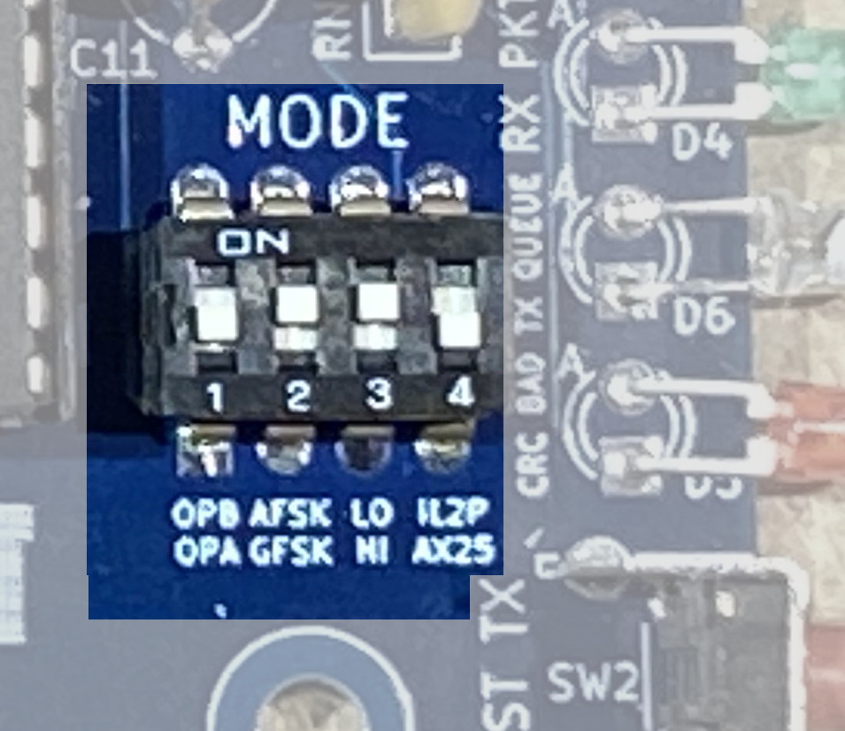
|
Beware that the silkscreen label around the MODE switch is no longer relevent.
We made that label when we only had four mode selections and were trying to guess what the future of the product would be. oops.
|
The A4 has a MODE switch to select the data rates used over the air.
As of vX.39 there are 16 modes available on NinoTNC.
See chapter 4 for a full list of the modes the NinoTNC A4 can do.
The TNC can do straight AX.25 packet protocol for compatibility, or can do Improved Layer 2 Protocol which is a forward error correction mode.
Using IL2Pc mode, the NinoTNC still talks to your host computer using KISS in the AX.25 form, but does some rearrangement of the bits and adds parity bits used in receive to recover packets that may have bit errors.
When any of the 4 MODE switches are changed, the NinoTNC will reset, show the 4 LED sweep pattern back and forth once, and then the TNC will encode and decode as instructed by the switches.
If the MODE switch settings are moved to an "expansion" or non-supported setting, the LED sweep may repeat indefinitely and the NinoTNC will not receive or transmit packets.
Move the MODE switches to a valid mode.
Not all NinoTNC MODE settings may be legal in your country or even possible in your universe.
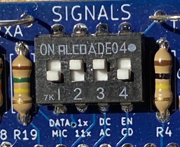
14-2. SIGNALS Switch
|
The signals switch affects transmit and receive audio, and also enables an external inhibit input.
Pushing the switch toward the edge of the board is ON and also the "1" position.
Pushing the switch toward the TARPN logo at the bottom of the board is OFF, and also the "0" position.
|
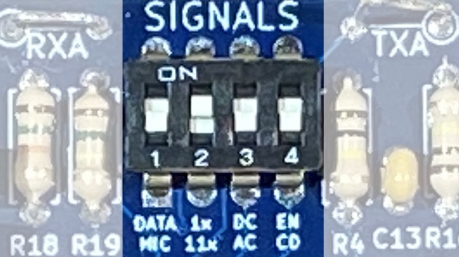
|

|
- switch 1 - Data vs Mic - NinoTNC transmit audio range selection
The Data position, ON, increases the TXA level so the TX-DEV potentiometer adjustment is in the range needed by the Data radio.
If the switch is in the OFF or MIC position, then the audio is reduced to the range needed by a microphone-level-input radio.
MIC range is 0-200mV, DATA range is 0-2.2V p-p.
- switch 2 - 1x vs 11x - NinoTNC receive sensitivity range selection
The ON, 1x position is about the right level for a speaker output, and is also appropriate for a data radio output.
The OFF, 11x position is new for the NinoTNC A4 and is used for radios which have a very low level of receive audio.
This is ideal for some of the Kenwood transcivers (TM-221A) having receive audio available on the microphone connector.
It may also be useful for radio hacks where the receive audio is obtained from interesting points inside the radio.
- switch 3 - DC vs AC - Transmit audio coupling control
This controls the coupling of the transmit audio to the radio.
The ON, DC position connects the output of the NinoTNC transmit amp directly to the DE9 TX pin.
There is a DC offset on the NinoTNC output such that at maximum output the negative going side of the output waveform is slightly above ground and the positive going side of the output waveform is just less than 3.3 volts.
The OFF, AC position inserts a capacitor between the output of the NinoTNC, at the wiper of potentiometer RV1, and the transmitter, creating a gap in the ciruit and preventing the op-amp's 1.8VDC voltage offset from being presented to the transmitter.
Having the capacitor in series in the transmit audio circuit is called AC coupling and is the standard case for the NinoTNC A2 and A3.
This allows the neutral condition of the transmit audio waveform to float to the level presented by the transmitter.
If measured without the transmitter connected, the audio waveform would appear to be ground centered.
The ON, DC position shorts out the capacitor which allows the TXA signal from the NinoTNC to flow directly to the transmitter.
If the transmitter is already AC coupling the input transmit audio, having an additional AC coupling capacitor in series will only impair the frequency response of the transmitted audio.
Usually this switch is left in the DC coupling position, 1, or ON, and is only set to AC coupling in specific cases, perhaps as recommended by the transceiver manufacturer.
Tait radios, when used with the data connector, are unhappy in the DC mode and will distort their transmit audio at the low-side of the wave form.
- switch 4 - EN vs CD -- External Carrier Detect
This switch, when slid to the ON/1/"EN" position will connect pin 2 of the DE9 connector to a GPIO on the CPU.
This option is to allow an external device to block the TNC from transmitting.
When set to ON/1/"EN", the TNC will inhibit transmit (and the DCD LED will light) when pin 2 of the DE-9 connector is grounded.
Use case: some dual-receive radios like TM-V71A can have an APRS system on one band and voice on the other.
This feature allows such a radio to inhibit the TNC from transmitting while the voice band PTT is active.
Leave in the OFF/0 position unless you are using external transmit inhibit.
Examples:
0110 - off on on off
1200 baud FM voice radio, Mic Tx and Speaker Rx connector
Also for A4-assembly loop-back test.
|
1100 - on on off off
Some Data radios and radios with 1v p-p packet-input
Tait TM8xxx radios with data connector.
|
|
|
|
0000 - off off off off
Kenwood TM mobile radio, Mic Tx audio, get Rx audio from mic connector.
Note: This isn't a recommendation for using the Mic connector Rx audio, but we discovered the Rx audio from the sample radio was low voltage P-P so we added the 11x gain mode (switch 2 OFF) to support it.
This might also be useful when tapping discriminator audio in a hacked transceiver?
An oscilloscope would be a good tool to use when experimenting with this.
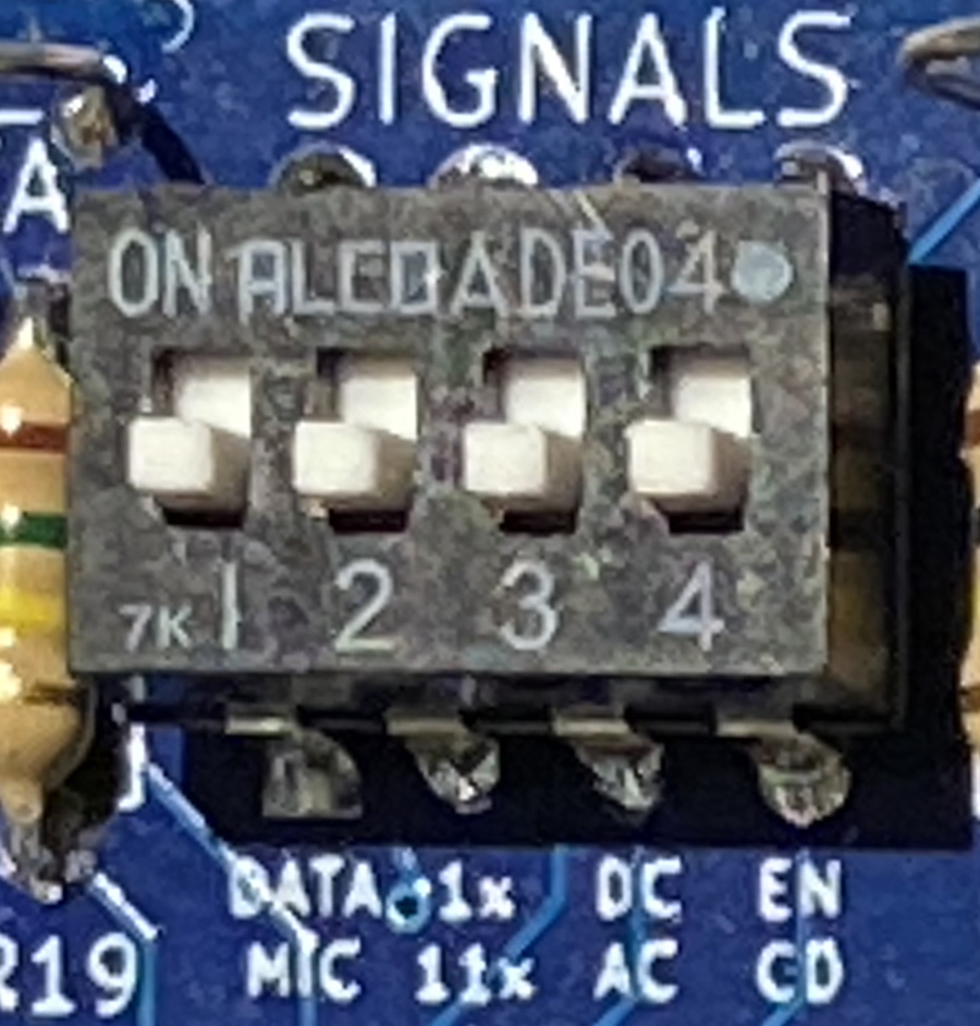
|
1110 - on on on off
Yeasu FTM3100R audio from internal connection points.
The transmit audio benefits from being DC coupled.
The TX DEV potentiometer will be turned up almost all the way.
|
15. V1-SMT-Specific Instructions
The V1-SMT board has a 6-bit DIP switch supporting mode settings and audio settings.
In addition there is a slide switch directing two audio input pins "12" and "96" into the NinoTNCs receive audio processing.
More information is available on
the RPC-Electronics.COM website.
15-1. 12-96 Slide Switch for Audio Input

Push the switch toward "96" to use with a radio set to 9600 audio.
Push the switch toward "12" to use with a radio set to 1200 audio.
15-2. Six-Bit DIP Switch
The V1-SMT-NinoTNC has a 4 Mode switches to select the data rates/encoding used over the air.
As of vX.39 there are 16 modes available on NinoTNC.
See section 4 for a full list of the modes the NinoTNC A4 can do.
The TNC can do straight AX.25 packet protocol for compatibility, or can do Improved Layer 2 Protocol which is a forward error correction mode.
Using IL2Pc mode, the NinoTNC still talks to your host computer using KISS in the AX.25 form, but does some rearrangement of the bits and adds parity bits used in receive to recover packets that may have bit errors.
When any of the 4 MODE switches are changed, the NinoTNC will reset, show the 4 LED sweep pattern back and forth once, and then the TNC will encode and decode as instructed by the switches.
If the MODE switch settings are moved to an "expansion" or non-supported setting, the LED sweep may repeat indefinitely and the NinoTNC will not receive or transmit packets.
Move the MODE switches to a valid mode.
Depending on the firmware, some MODE swttings may be marked as expansion but will be redundant with a specified setting, or may be a test mode.
Beware of unspecified behavior when using an unspecified MODE switch setting.
Not all NinoTNC MODE settings may be legal in your country or even possible in your universe.

The 16 MODE switch settings are using the MODE3, MODE2, MODE1, MODE0 switches. If MODE1 is toward the center of the unit, it is a "1".
With the other three switches toward the edge of the board, that would be written down as "0010".
The image above shows the switches at "011001" but the MODE3 → MODE1 switches are set to "0110".
| 0000 | 9600 GFSK AX.25 | G3RUH - 1990s 9600 TNCs |
| 0001 | 19200 C4FSK IL2Pc | New mode as of version 4.41- requires very good quieting |
| 0010 | 9600 GFSK IL2Pc | 9600 baud IL2Pc |
| 0011 | 9600 C4SK IL2Pc | New mode as of version 4.41 - This is designed for UK market and requires very good quieting |
| 0100 | 4800 GFSK IL2Pc | 4800 baud GFSK IL2Pc |
| 0101 | 3600 QPSK IL2Pc | narrow FM mode, 1800 symbols/sec. Designed to pass through standard FM audio filter |
| 0110 | 1200 AFSK AX.25 | Generic 1990s packet - use for APRS |
| 0111 | 1200 AFSK IL2Pc | backward compatible with IL2PC |
| 1000 | 300 BPSK IL2PC | 500 Hz occupied bandwidth SSB mode |
| 1001 | 600 QPSK IL2Pc | 500 Hz occupied bandwidth SSB mode |
| 1010 | 1200 BPSK IL2Pc | 2400 Hz occupied bandwidth |
| 1011 | 2400 QPSK IL2Pc | 2400 Hz occupied bandwidth |
| 1100 | 300 AFSK AX.25 | SSB mode (legacy from 1990s KAM and PK-232) |
| 1101 | 300 AFSK IL2P | deprecated after 3.41/4.41 |
| 1110 | 300 AFSK IL2Pc | 1600/1800 Hz tone FSK. Filtered for 500 Hz occupied bandwidth |
| 1111 | KISS SETHW | See chapter 4 |
15-3. Transmit and Receive Audio Switches
The signals switches affects transmit and receive audio.
- Mic/Data - NinoTNC transmit audio range selection
The Data position, ON, increases the TXA level so the TX-DEV potentiometer adjustment is in the range needed by the Data radio.
If the switch is in the OFF or MIC position, then the audio is reduced to the range needed by a microphone-level-input radio.
MIC range is 0-200mV, DATA range is 0-2.2V p-p.
- 11x/1x - NinoTNC receive sensitivity range selection
The ON, 1x position is about the right level for a speaker output, and is also appropriate for a data radio output.
The OFF, 11x position is used for radios which have a very low level of receive audio.
This is ideal for some of the Kenwood transcivers (TM-221A) having receive audio available on the microphone connector.
It may also be useful for radio hacks where the receive audio is obtained from interesting points inside the radio.
|

|
16. 9600 baud Receive Eye Pattern
You can get the 9600 receive eye diagram at the RXA scope probe loop.
Set the trigger for 1.65 volts
17. USB Data Dump -- GETALL Message
Each time the TX-TEST button is released, the NinoTNC will generate and send a block of data to the host computer.
If the host computer is displaying or logging the monitored packet data, this message may appear to come in over the air, or appear to be transmitted.
It actually is not going over the air or taking up channel time, though the TX-TEST button release will also generate an over-the-air test message.
The NinoTNC will automatically send this message back to the host computer periodically.
This is subject to change. Please write to our email reflector if using this command.
The TARPN project uses this data to diagnose node and network operation.
The NinoTNC can also send this message back to the host on demand, using a KISS command 0x0B (GETALL).
The data contains fields separated by the "=" sign.
Each field has a 2 digit hexidecimal ID code, followed by 0 to 8 digits of hexidecimal data, in most cases, or is in ASCII text where specified.
00 firmware version (4 character ascii text string)
01 KAUP8R -- KISS Accessible User Programmable 8-character Register/Serial Number. Erased by bootloader.
02 up time in milliseconds
03 board id (0 = A0, A1; 1 = A2; 2 = A3; 3 = A4r0 (all pre-release A4); 4 = A4 or SMT)
04 switch positions (some bit-manipulation required to match with actual switch)
05 there is no #5
06 configuration mode
07 AX.25 received packet count
08 IL2P correctable received packet count
09 IL2P uncorrectable received packet count
0A transmit packet count
0B preamble word count (multiply by 16 and divide by baud to get preamble time in seconds)
0C main loop cycle count since boot
0D PTT On time in milliseconds
0E DCD On time in milliseconds
0F Received data byte count (excludes preambles, flags, syncwords, etc)
10 Transmit data byte count (excludes self-generated ID beacons, preambles, etc)
11: Number of erroneous bytes corrected by IL2P FEC
If the TNC doesn’t reboot for other reasons, it will reboot itself after 23 days to prevent millisecond counter rollover (32 bits).
Example:
------------------------------------------  p6   2020-10-12 22:28:57
KK4HEJ-15>IDENT<UI C>:
=00:2.76=01:13FAAAAut=02:0010FB70=03:00000001=04:00000002=06:00000001=07:00000000=08:00000011=09:00000000=0A:00000022=0B:00000012=0C:02157BDF
Note that when the TESTTX button is released, a slightly modified version of this data is output.
Instead of numerical register descriptions, the TESTTX output will have text labels for each register:
01:04:38R KA2DEW-2>IDENT Port=4 <UI C>:
:Test Packet=
FirmwareVr:3.01=SerialNmbr:xxFwQR9G=UptimeMilS:09CC8471=BrdSwchMod:020A0003=AX.25RxPkts:00000100=
IL2PRxPkts:000013C1=IL2PRxUnCr:000000A2=TxPktCount:00002C76=PreamblCnt:00000009=LoopCycles:A0E0E6A5
18. G8BPQ node confing
For non-TARPN nodes built with G8BPQ, you must define a port to talk to the TNC in the bpq32.cfg file.
The definition will be slightly different for 1200 baud vs 9600 baud and may also be tailored for the radio.
Here is an example G8BPQ port definition for 1200 baud using a 2m ham radio:
PORT
PORTNUM=1
ID=p2p link to k1qsy-2
TYPE=ASYNC
PROTOCOL=KISS
FULLDUP=0
COMPORT=/dev/ttyUSB1
SPEED=57600
CHANNEL=A
PERSIST=225
SLOTTIME=20
TXTAIL=1
QUALITY=1
MINQUAL=81
MAXFRAME=1
FRACK=6000
RESPTIME=40
RETRIES=20
PACLEN=236
UNPROTO=ID
L3ONLY=0
DIGIFLAG=0
DIGIPORT=0
USERS=1
IGNOREUNLOCKEDROUTES=1
ENDPORT
Here is a G8BPQ port definition for 9600 baud using a Tait TM8105 data radio:
PORT
PORTNUM=1
ID=p2p 9600 link to k1qth-2
TYPE=ASYNC
PROTOCOL=KISS
FULLDUP=0
COMPORT=/dev/ttyUSB0
SPEED=57600
CHANNEL=A
PERSIST=225
SLOTTIME=20
TXTAIL=1
QUALITY=1
MINQUAL=81
MAXFRAME=1
FRACK=2000
RESPTIME=20
RETRIES=20
PACLEN=202
UNPROTO=ID
L3ONLY=0
DIGIFLAG=0
DIGIPORT=0
USERS=1
IGNOREUNLOCKEDROUTES=1
ENDPORT
19. 3d-Printed Enclosures
Click here to go to the 3d-print-ninotnc web page.


20. NinoTNC-based Test Modes Bit-Error-Rate + Beacon
These features are initiated on a NinoTNC by holding the TEST-TX button for 10 seconds starting from the NinoTNC already running.
These features continue to be active even if the NinoTNC power is removed and reapplied.
To enter a test mode, make sure power is applied to the NinoTNC and after the LEDs do their sweep.
Now press and hold the TEST-TX button.
After 10 seconds of power application, the LEDs will start to slowly illuminate, from left to right, one per second.
Release the TEST-TX button when the appropriate LEDs are lit.
- 3 LEDs = Bit Error Rate Receive packet analyzer CRC+Queue+Transmit
- 4 LEDs = Bit Error Rate test-packet-generation CRC+Queue+TxGoodPacket+Transmit
- 5 LEDs = Linktest test-packet-generation CRC+Queue+TxGoodPacket+DCD+Transmit
To cancel one of these modes, press and release the TEST-TX button again.
20-1. Linktest test-packet-generation
The TNC will send uniquely numbered packets without direction from a host.
This feature is available in every MODE (i.e. bitrate and IL2P/AX.25 selection).
The TNC will generate and transmit numbered packets with a 1 second break in between packet transmissions.
The test-packet-generation will go on until the user presses the TEST_TX button again (even through mode changes and power downs).
The TNC is not listening to the KISS port, nor receiving packets, during this test-packet-generation.
The TNC uses the last stored callsign sent by the host as its own callsign for the purpose of building these packets.
So after programming the TNC, it's best if it has sent a few UI frame packets in normal operation so it can harvest a callsign to put in the header of the linktest packets.
The default callsign is N9600A-3.
20-2. Bit Error Rate Transmit Mode:
The TNC can now send a 2-minute long string of uninterrupted bits encoded in a way that can be evaluated for bit errors.
This mode is only available in the AX.25 protocol switch settings (right-most MODE switch off) due to memory structures needed to generate the bitstream.
However, this mode can be used in all modulation selections (GFSK, AFSK, DPSK).
On release of the TEST-TX button with the first 3 LEDs and the TX LED illuminated, the TNC will transmit a test packet, then start the bitstream transmission about 1 second later.
Note that this 2-minute transmission will probably exceed the PTT timers on modern radios.
20-3. Bit Error Rate Receive Mode:
In conjunction with the BER transmit mode, the TNC can receive the bitstream and count errors.
To use this mode, first hook the TNC up to a host that can monitor KISS frames from the TNC.
The TNC will send bit report frames to the host computer over USB, every second for the next 10 minutes.
The report frames will include a demodulator number (the AFSK mode currently has 2 demodulators with different equalization), the total bits received since the mode was entered, and the bits received in error.
These rolling counts will continue to increase while the mode is active.
The counts will stay at zero until about 1.5 seconds after the mode starts to let things stabilize.
The mode can be exited at any time by pressing the TEST_TX button.
When the reported Bit Error Count is not changing (or changing very little), the link has a low BER.
Note that in GFSK modes, the reported Bit Error Count is twice the number of actual pulses received in error over the air.
This is related to the LFSR scrambling polynomial used by the G3RUH encoder, it has two feedback taps.
So each bit error affects two bits in the data bitstream.
I expect the Bit Error Count will always advance by 2 in practice.
This isn't extremely important, as bit errors are usually interesting in terms of their order of magnitude.
21. tnc-tools Python Tools For Configuring and Querying NinoTNC
Nino wrote some Python programs that are used to configure, query, and test the NinoTNC.
The
Github web site for these tools is here.
These tools require Python3 and Pyserial to run.
21-1. n9600a-cmd.py
Usage:
python3 n9600a-cmd.py <serial device> <optional value>
Send command frames to an N9600A NinoTNC attached to the specified serial port. Invoke without arguments for a list of available commands. The serial number of the TNC must be clear before it can be set. Use CLRSERNO to clear it.
Example without argument:
C:\github\tnc-tools>py -3 n9600a-cmd.py com18
Not enough arguments. Usage prototype below.
python3 n9600a-cmd.py <serial device> <command> <optional value>
Available commands:
CLRSERNO               : Erases the stored TNC serial number. Perform before SETSERNO.
SETSERNO xxxxxxxx      : Sets the TNC serial number, value is 8 ASCII characters.
GETSERNO               : Queries and displays the TNC serial number.
SETBCNINT nnn          : Sets the beacon interval, value is minutes 0 to 255. 0 disables.
GETVER                 : Queries and displays the TNC firmware version.
STOPTX                 : Stop the current transmission and flush queues.
GETALL                 : Dump diagnostic data.
SETPERSIST nnn         : Set CSMA persistance value, 0 to 255.
SETSLOT nnn            : Set CSMA slot time in 10mS units, 0 to 255.
Example GETVER:
C:\github\tnc-tools>py -3 n9600a-cmd.py com18 getver
4.21
Example SETSERNO and GETSERNO:
C:\github\tnc-tools>py -3 n9600a-cmd.py com18 setserno ABc12D9x

C:\github\tnc-tools>py -3 n9600a-cmd.py com18 getserno
ABc12D9x
21-2. kiss-listen.py
Usage:
python3 kiss-listen.py <serial device> <baud rate>
Listen for kiss frames on the specified serial port and display them on the console. Each frame is displayed as printable characters, raw byte values, and an AX.25 decode. Frames are given a date/time stamp, as well as a count index. Number of bytes in the frame is displayed as well. Press CTRL-C to exit.
Example:
C:\github\tnc-tools>py -3 kiss-listen.py com6 57600
Opened port com6

-- 2023-03-15 14:00:19.604402 frame number: 1 byte count:  70
...d...j..h..... |  0 96 82 64 88 8A AE 6A 96 96 68 90 8A 94 E9  3
.GFSK 9600 IL2P  | F0 47 46 53 4B 20 39 36 30 30 20 49 4C 32 50 20
-120dBm 1 ~EBB&P | 2D 31 32 30 64 42 6D 20 31 20 7E 45 42 42 26 50
4"PPhaB'|%<kSHcp | 34 22 50 50 68 61 42 27 7C 25 3C 6B 53 48 63 70
FI^i;}           | 46 49 5E 69 3B 7D
- AX.25 Decode:
To:KA2DEW-5, From:KK4HEJ-4, Control: UI, PID: No Layer 3
GFSK 9600 IL2P -120dBm 1 ~EBB&P4"PPhaB'|%<kSHcpFI^i;}
21-3. kiss-ax25-ui.py
Usage:
python3 kiss-ax25-ui.py <serial device> <baud rate> <src call-ssid> <optional dest call-ssid> <optional payload>
Generate a single AX.25 un-numbered information packet, like an APRS packet, and send it to the specified serial port with KISS encapsulation.
Only the serial device, baud rate, and source callsign arguments are requred. Destination callsign will default to "IDENT-0" if omitted.
Payload argument should be enclosed in double quotes if it contains whitespace.
This utility is handy for setting the source callsign on a NinoTNC, send one packet from your callsign and the TNC will use it for subsequent test packets when the TEST_TX button is pressed.
Minimum argument example:
C:\github\tnc-tools>py -3 kiss-ax25-ui.py com18 57600 kk4hej-4
At the receiver, this generates a packet that looks like:
-- 2023-03-15 14:13:13.365019 frame number: 27 byte count:  17
......@`..h..... |  0 92 88 8A 9C A8 40 60 96 96 68 90 8A 94 E9  3
.                | F0
- AX.25 Decode:
To:IDENT-0, From:KK4HEJ-4, Control: UI, PID: No Layer 3
Example with a payload:
C:\github\tnc-tools>py -3 kiss-ax25-ui.py com18 57600 kk4hej-4 aprs ":payload can be an APRS information field"
Received packet:
-- 2023-03-15 14:16:40.761511 frame number: 30 byte count:  58
.....@@`..h..... |  0 82 A0 A4 A6 40 40 60 96 96 68 90 8A 94 E9  3
.:payload can be | F0 3A 70 61 79 6C 6F 61 64 20 63 61 6E 20 62 65
 an APRS informa | 20 61 6E 20 41 50 52 53 20 69 6E 66 6F 72 6D 61
tion field       | 74 69 6F 6E 20 66 69 65 6C 64
- AX.25 Decode:
To:APRS-0, From:KK4HEJ-4, Control: UI, PID: No Layer 3
:payload can be an APRS information field
kiss-ax25-ui-batch.py
Usage:
python3 kiss-ax25-ui-batch.py <serial device> <baud rate> <src call-ssid> <dest call-ssid> <frame count> <payload text> <payload length> <frame interval>
Generate a sequence of un-numbered information frames and send them to the serial port at the specified interval.
Useful for testing links and bench testing TNCs and radios.
Program accepts a payload text argument, as well as a payload length argument.
If the payload length requested is longer than the supplied payload text (plus an added frame index) then the program extends each payload with random printable characters to meet the requested payload length.
Example:
C:\github\tnc-tools>py -3 kiss-ax25-ui-batch.py com18 57600 kk4hej-4 test 3 "-115dBm GFSK 9600 IL2P " 53 1
On the receive side:
C:\github\tnc-tools>py -3 kiss-listen.py com6 57600
Opened port com6

-- 2023-03-15 14:26:21.038707 frame number: 1 byte count:  70
.....@@`..h..... |  0 A8 8A A6 A8 40 40 60 96 96 68 90 8A 94 E9  3
.-115dBm GFSK 96 | F0 2D 31 31 35 64 42 6D 20 47 46 53 4B 20 39 36
00 IL2P 1 S@l/aG | 30 30 20 49 4C 32 50 20 31 20 53 40 6C 2F 61 47
vuH<s,2Td/$UYg/  | 76 75 48 3C 73 2C 32 54 64 2F 24 55 59 67 2F 20
f5hER*           | 66 35 68 45 52 2A
- AX.25 Decode:
To:TEST-0, From:KK4HEJ-4, Control: UI, PID: No Layer 3
-115dBm GFSK 9600 IL2P 1 S@l/aGvuH<s,2Td/$UYg/ f5hER*

-- 2023-03-15 14:26:22.065947 frame number: 2 byte count:  70
.....@@`..h..... |  0 A8 8A A6 A8 40 40 60 96 96 68 90 8A 94 E9  3
.-115dBm GFSK 96 | F0 2D 31 31 35 64 42 6D 20 47 46 53 4B 20 39 36
00 IL2P 2 J`yPUP | 30 30 20 49 4C 32 50 20 32 20 4A 60 79 50 55 50
KBe!QP,&DRFX$s(_ | 4B 42 65 21 51 50 2C 26 44 52 46 58 24 73 28 5F
5I:3cq           | 35 49 3A 33 63 71
- AX.25 Decode:
To:TEST-0, From:KK4HEJ-4, Control: UI, PID: No Layer 3
-115dBm GFSK 9600 IL2P 2 J`yPUPKBe!QP,&DRFX$s(_5I:3cq

-- 2023-03-15 14:26:23.078650 frame number: 3 byte count:  70
.....@@`..h..... |  0 A8 8A A6 A8 40 40 60 96 96 68 90 8A 94 E9  3
.-115dBm GFSK 96 | F0 2D 31 31 35 64 42 6D 20 47 46 53 4B 20 39 36
00 IL2P 3 ohhGn) | 30 30 20 49 4C 32 50 20 33 20 6F 68 68 47 6E 29
8[*r:zqfyG!R9zko | 38 5B 2A 72 3A 7A 71 66 79 47 21 52 39 7A 6B 6F
=W%.mJ           | 3D 57 25 2E 6D 4A
- AX.25 Decode:
To:TEST-0, From:KK4HEJ-4, Control: UI, PID: No Layer 3
-115dBm GFSK 9600 IL2P 3 ohhGn)8[*r:zqfyG!R9zko=W%.mJ
Interesting Reads from G3RUH and others
AMSAT article 109 by G3RUH
WD6EHR 9600 baud handbook