Robust Power for Raspberry PI
|
This page discusses a very inexpensive system for using a GelCel to provide stable power to the Digital Section of a TARPN node.
This involves creating a UPS (Uninteruptable Power Supply) to the Raspberry PI.
Low cost power switchover device
Total parts cost is about $45 at retail if you have to buy a $15 Gel Cel.
I have been able to buy the gel-cel for $120 for 10 of them using Amazon.
Perhaps you can replace the gel-cel in one of your UPSs and use it's old gel-cel for this circuit.
This schematic at the bottom of this page shows a simple battery floater circuit and switchover to power a USB power supply.
The purpose of this is to keep the Raspberry PI up through power drop-outs and while moving the network cabinet.
A 4 amp gel cell should run the raspberry PI for several hours or more.
With my circuit it would take a day or more to recover the battery after a couple of hours of outage.
That's ok because I don't expect to be on battery very often.
The resistor should be such that even if the battery was a dead short, it wouldn't draw enough power to hurt anything.
I figured about 200 ohms was good. Anything above 200 up to 1k is probably adequate but 200 is a good lower limit.
200 ohms will get you about 70mA of current flow even if the battery were shorted.
70mA at 14v is about 1 watt of power so you need at least 1 watt of resistor rating.
I took several 3.3Kohm 1/4watt resistors and used them in parallel.
Larger resistor values will cause the gel cel to charge slower but will also generate less heat.
My later implementation uses a 50 ohm power-resistor with 10 watts rating.
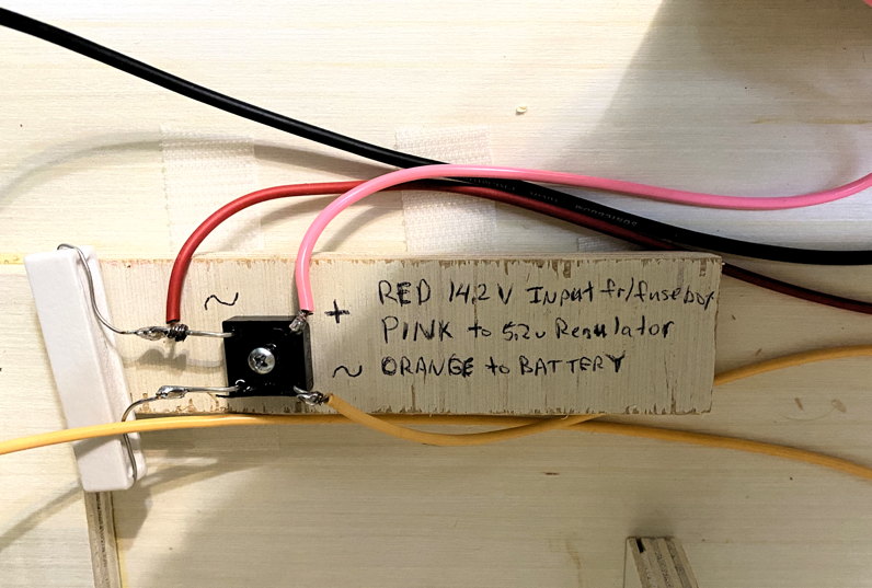
Important: 14.2 V is required as the feed into the diode switch so the float voltage onto the SLA Gel-Cel is idealized.
We had been using an HP server supply modified to serve 14.2 VDC, and that was ideal.
But a 13.8 V or lower supply, to feed the radios, is now cheaper and much more common, so instead of using a 14.2 V supply to the entire system, we add a cheap, readily available off-the-shelf Meanwell brand, 14.2 V supply to feed just the Raspberry PI/digital section (including backup battery) of the node.
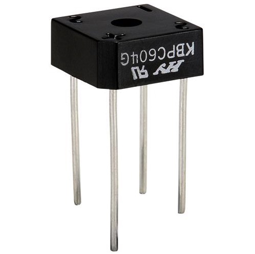
The schematic needed 3 diodes.
The nice thing about the bridge rectifier is that it gave me the diodes I needed in a single package and it had a screw mounting hole.
I mounted the bridge to the wooden wall of my cabinet.
If you get a bridge rectifier with 1 amp diodes or larger, this is fine.
|
|
|
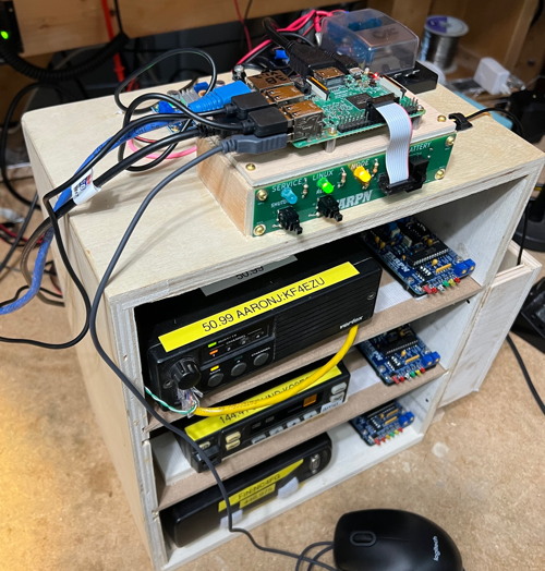
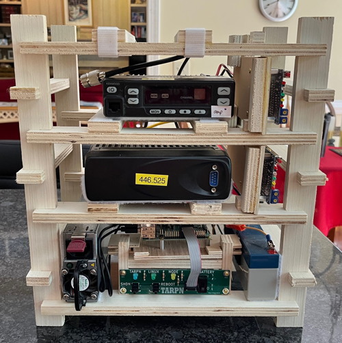
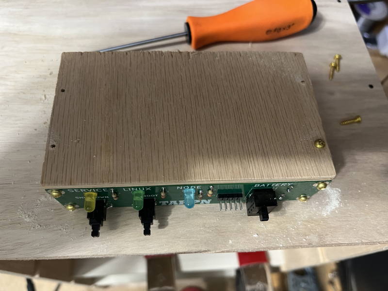
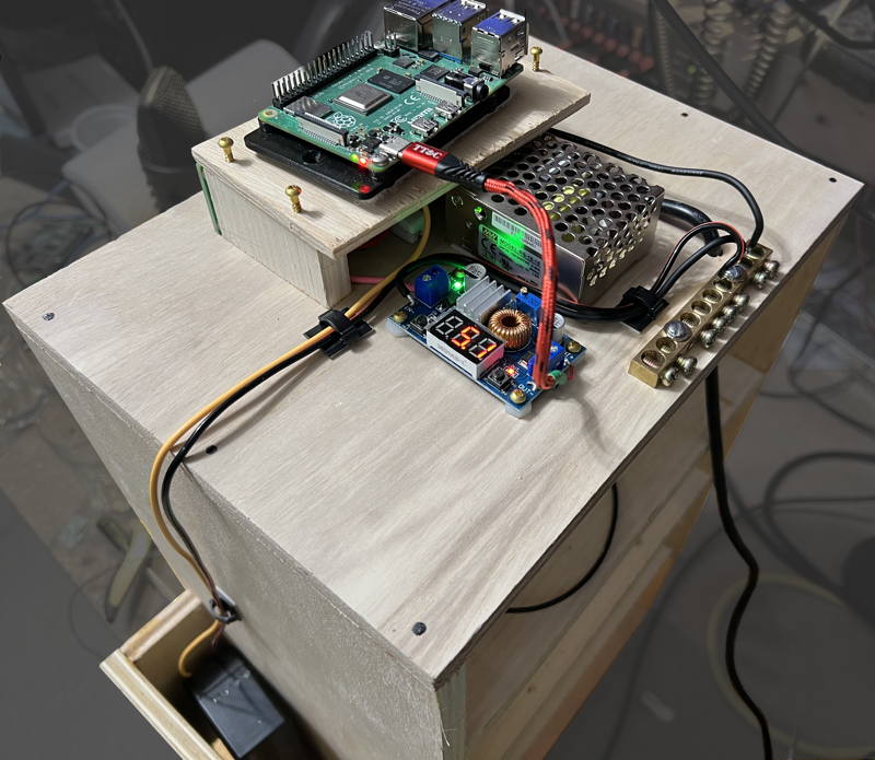
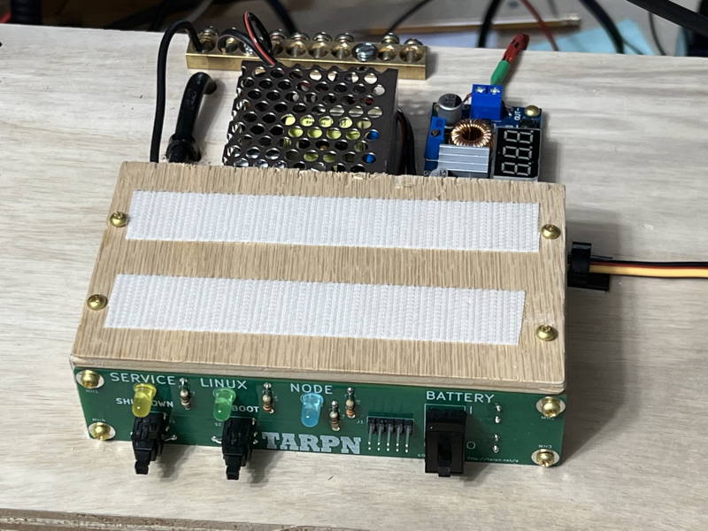
Above:
example fully assembled node boxes.
Top is a KM4EP cabinet.
Bottom is an NC4FG cabinet.
|
|
5.2 V regulator
The Raspberry PIs are most happy with 5.2 V power feed via the USB input to the Raspberry PI.
They are also most happy with a glitch free uninteruppted 5.2V.
Even a 1/1000th of a second glitch to below 5V seems to lead to SDcard corruption.
The solution, since we're running on 12V (mostly) for the radios, is to take the 12V and regulate it down to 5.2V.
The cheap way to do that is to use off-the-shelf 12V to 5.2V devices that are made in the orient.
These can be from $2 to $16.
The ideal solution would have screw terminals for power input, and a USB connector for power output.
We were able to buy such a device for several years but the manufacturar, DROK, revised the model a couple of years ago with one whose USB output, while still variable, is disabled by default when power is applied to the inputs to the device.
It requires a menu operation to turn the power on.
This is not useful to us.
There are several off the shelf boards available from hundreds of random name-changing vendors via Amazon, eBay, Aliexpress, that are specified to take 12-15V or wider and regulate it down to a variable output including 5.2V and put it out on screw terminals or solder pads.
In all cases we now have to find a connection into the Raspberry PI.
Again, USB input to the PI is most convenient.
So now, besides finding an appropriate regulator, we need to put together a USB cable that is two wires in, and USB plug out.
The cheapest way to do this is to take a USB to USB cable and cut one end off.
The issue now becomes figuring out which wire in the USB cable connects to the 5V bus on the PI and which connects to Ground.
Unfortunately, the selection of a regulator, and the analysis of the USB cable, must fall to the individual node-box robust-supply builder.
Perhaps, optimally, your club can get together and do a group buy and then solve the problem once for multiple builds.
The description to search on is
"
DC-DC DROK Power Supply Module LM2596"
I recommend not using price as your sole selection criteria.
Some price between $4 and $20 can be expected.
If you are going to do a group project, it may be worth buying several models and then once mastery is acheived, do a group buy immediately before the shifty suppliers shift supplies, or shift supplier name to another shifty sounding name.
You think I'm kidding? The supplier names on Amazon right now are Dafurui, Valefod, Generic, Bulvack, Bankee.
This is the elusive discontinued DROK USB-output variable supply
It's key feature is the built-in always-on USB power output connector.
Beware that the new model of this has a default-off USB output.
The key visible difference between the models is the good model has a 4 digit LED display and the new (bad) model has an LCD display.
Warning..
Adjust the output voltage to 5.2 V before plugging in the Raspberry PI.
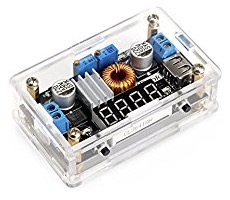
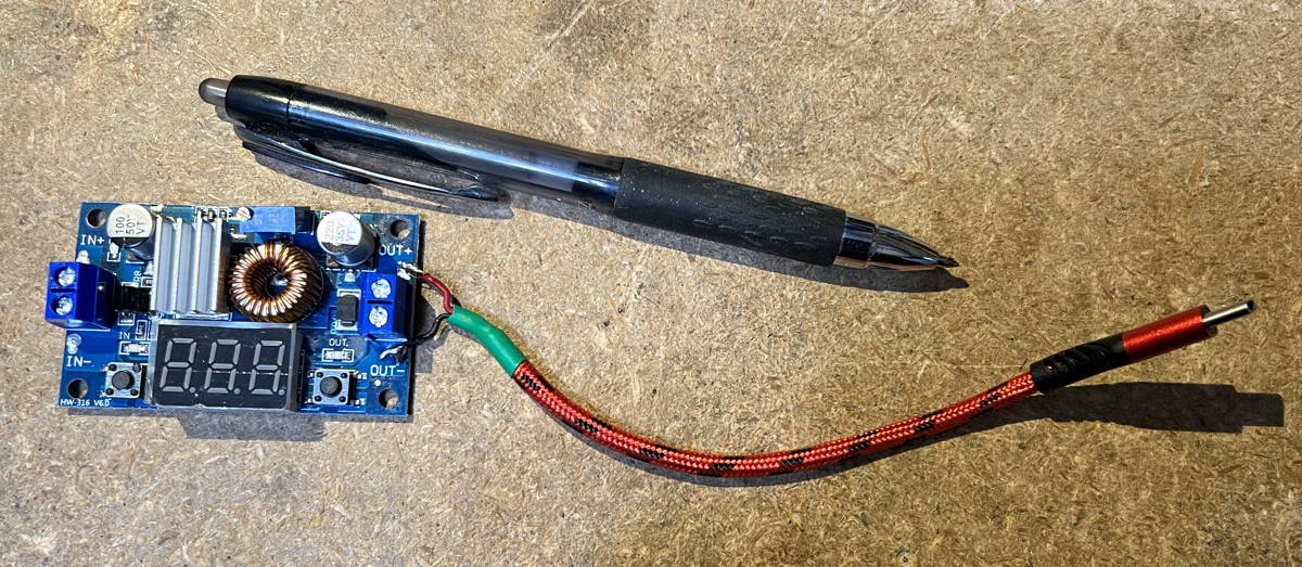
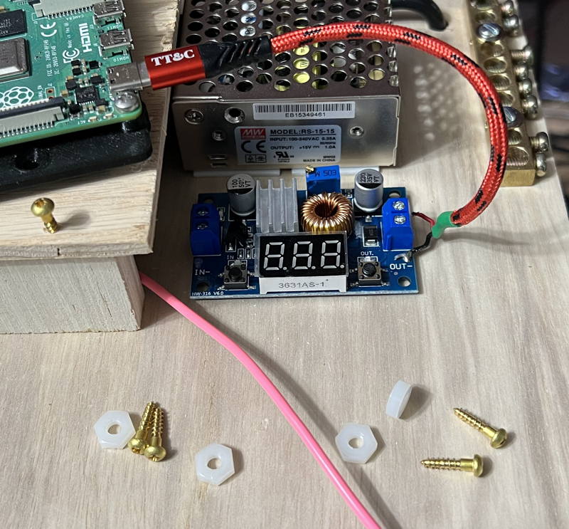
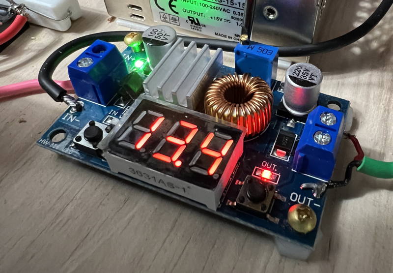
This is the unit I have been using when I could not get the now-discontinued unit.
This unit has both screw terminals and solder pads for input and output, and has a display that can (with only about 0.2V accuracy) show the input and output voltage.
It costs about $8 from Amazon, cheaper from other suppliers. But beware the cheaper.
Amazon has a hassle free return policy.
I picked up 20 of these boards by accident from an Aliexpress shifty vendor whose advertisement showed the desirable unit (with always-on-USB) and was asking $4 each.
So cheap! So I ordered 20 of them.
What I received 6 weeks later was a box full of this unit (same regulator/controller chip, but no USB output).
I called a foul on them to Aliexpress and, though it took a bit of arguing and incriminating photos/screenshots, Aliexpress made the vendor give me back my $80+ but the vendor didn't want to pay shipping to send the 20 units to Asia, so I got to keep them.
USB Cable modification
During final assembly you'll need to hook up a USB cable to the PI and to the output of the supply.
First we have to make a custom USB cable that attaches to the output of the regulator.
What I did is cut an off-the-shelf-cable such that there is about 6 inches of wire between the Raspberry PI end and where I cut.
Then strip the wire outer jacket back.
Insert a heat shrink tube, about an inch long, over the wire and push it away up toward the PI plug end.
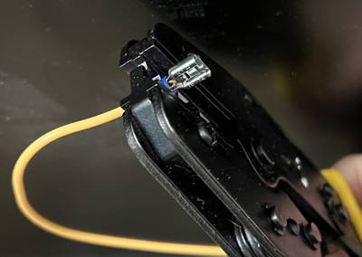
Now strip back the 4 wires inside the cable.
Plug the USB cable into the Raspberry PI.
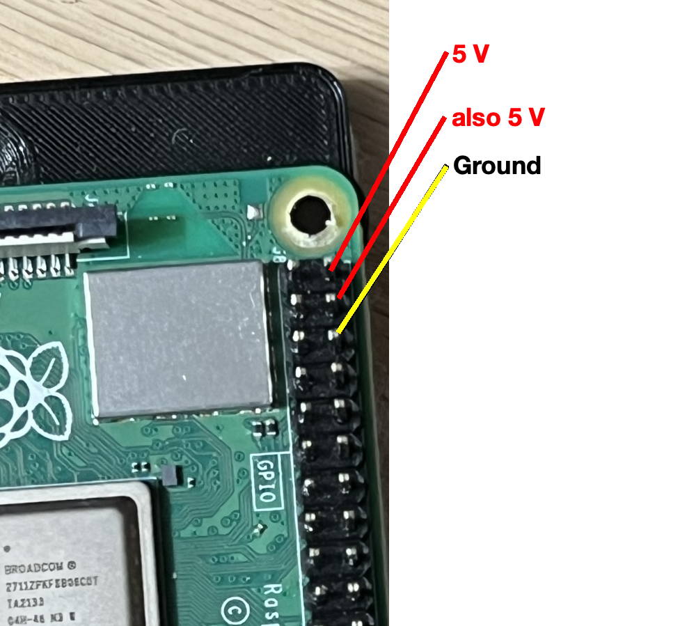
Refer to this diagram for test points on the Raspberry PI:
Use the V-O-M in ohms setting to check which wire is ground by measuring the resistance from the ground pin on the Raspberry PI's 40 pin expansion header to each of the 4 wires..
The lowest resistance should be nearly 0 ohms and that will be the ground wire.
Solder the discovered ground wire to the regulator's -V terminal on the OUTPUT side of the regulator card. (or tin and screw the wire to the output)
Use the V-O-M to find the 5 V wire, again by measuring ohms to the Raspberry PI's 40 pin header.
Solder or screw the 5 V wire to the supply at the +V terminal on the OUTPUT side of the regulator card.
After the wire cools where you soldered, move the heat shrink over the stripped end of the wire and shrink it to cover the unused two wires on the USB cable.
|
|
|
You will want the USB wire from your regulator to the PI to be really short.
6 inches is a good length.
If longer, the voltage at the PI will vary with processor or accessory load.
During PI operation using the desktop display, you could see a lightning bolt on the upper right of the display during boot, and that would indicate you are under-volts.
|

|
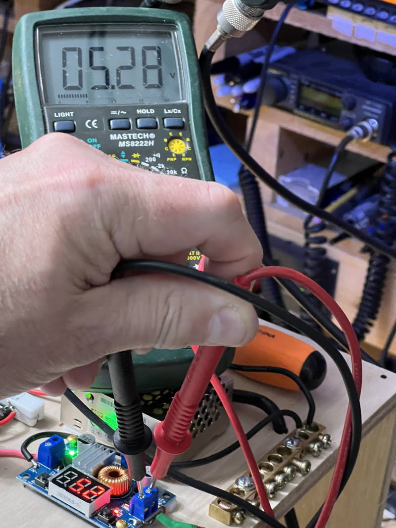
You should definitely use a V-O-M when setting the regulator's output voltage and
do not have the USB cable plugged into the Raspberry PI until you have set the regulator's output voltage.
Beware that the multi-turn potentiometers may only have a useful range in the middle of the 10 or 20 turn mechanical range.
That means that you may be turning the pot counterclockwise, i.e. down, several full turns before the output moves at all.
This is probably because the output range is 30 volts or so, but it won't affect the output until the adjusted-voltage is less than the input voltage, which in this case is going to be around 12 V.
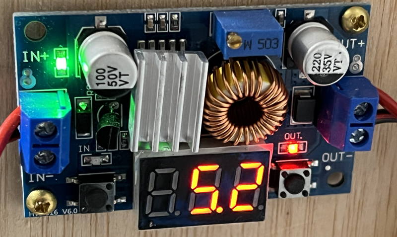
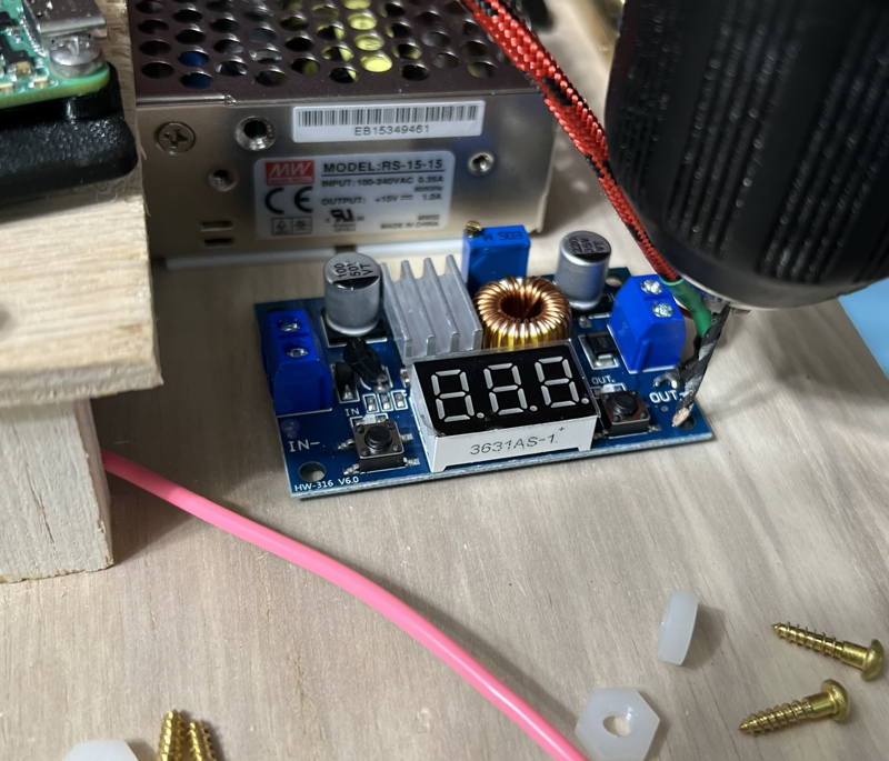
The buttons on the pictured model control if and what the numerical display shows.
One of the buttons turns the LED display on and off.
The other button selects which voltage is shown on the LEDs.
There is a small LED above each button that indicates whether you are seeing the INPUT (left) or the OUTPUT (right LED) voltage on the display.
Parts for the switchover/trickle charge circuit
Parts list:
- Gel Cel battery
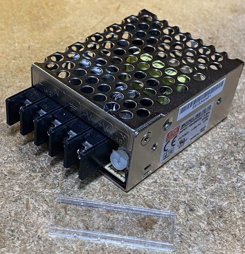
- Meanwell RS-15-15 Specifications [meanwell.com]
- DC-DC regulator device with 5.2 V adjustable output
- 6 or 7 inch short USB cable - Amazon has some 7 inch and .5 foot cables - any length cut down to 6" or so if home-brewing the regulator-output connection
- some scheme to mount the regulator (I use nylon #8 hex nuts McMaster-Carr 90089A305 (100) for $2.62)
- double face tape for permanently attaching the Meanwell to the top of a shelf within or on the top of your node cabinet.
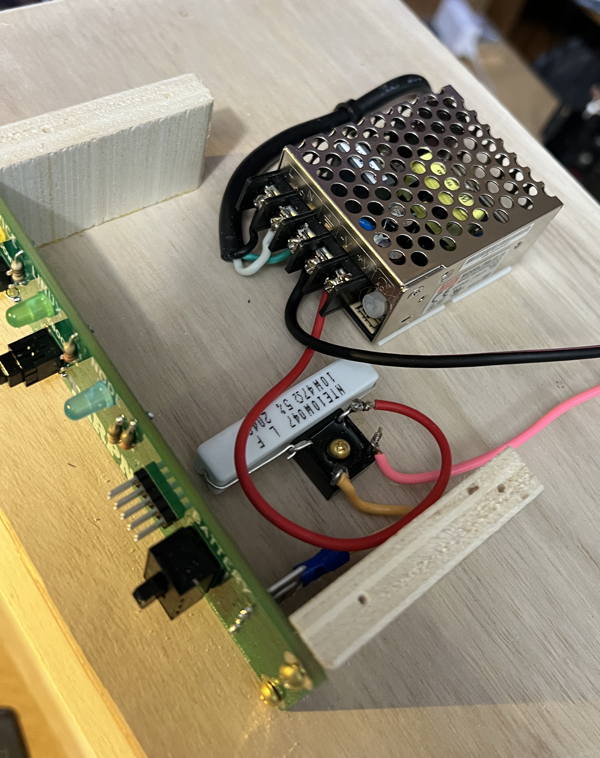
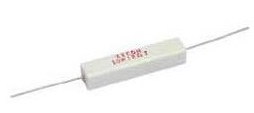
- 50 Ohm (+/- 10% on value) 5 or 10 Watt resistor -- the photos below show a 56 Ohm 5watt resistor.
- Bridge Rectifier
- (2) female Crimp-on lugs for the Gel Cel
- 3-foot of hookup wire, 16 to 20 AWG.
This wire passes at most 1 Amp at 14.2 VDC
- TARPN Control Panel or other switch
The Bridge rectifiers come from
Parts-Express and are 400V 6A Bridge Rectifier -- Part # 050-030
The resistors (I usually buy them in quantity and keep some in stock) come from
Parts-Express and are 47 Ohm 10W Resistor Wire Wound 5% Tolerance -- Part # 016-47
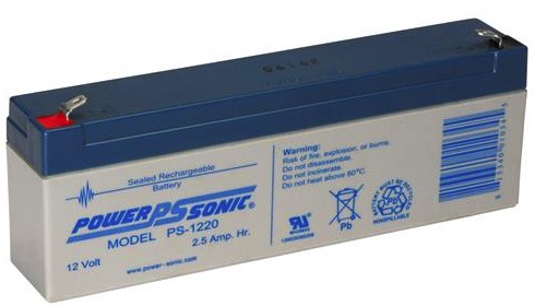
The gel cells I've used so far run from 2 to 4.5 amp-hour.
Here is my favorite model because it fits in the housings we've been using:
Parts Express has Power-Sonic PS-1220 Sealed Lead Acid Battery 12V 2.5Ah -- Part # 140-360
Amazon has also had these in quantity 10 for lower cost per unit.
The variable output 14.2 V power supply is a Meanwell RS-15-15
Mouser Meanwell RS-15-15
Digikey Meanwell RS-15-15
click to enlarge

Schematic of the robust power supply
Note that the AC to DC supply should have 14.2v output in order to float the GelCel propertly.
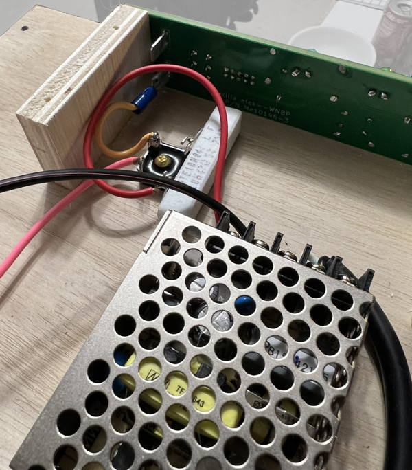
Drawing and photos showing method of constructing the robust power supply.
Here's the bridge rectifier and trickle-charge resistor.
Before proceeding:
- Unplug the Raspberry PI power from the Raspberry PI.
- Remove the memory SDcard from the Raspberry PI.
- turn off the battery switch and
- disconnect the positive lead from the battery.
- Hook the Meanwell to an AC power cord.
See detail on AC wiring, below.
- Tin and screw the red wire from your bridge rectifier circuit to the +V screw terminal.
- Tin and screw a black wire, 12" long should be enough, to the -V screw terminal.
- Carefully clip lead a Volt Ohm Meter to the black wire and to the orange wire from the bridge rectifier circuit.
- Set the V-O-M to measure 20V or more DC.
- Plug the AC cord into a switched outlet and turn it on.
- Observe the V-O-M reading, and adjust it to 13.8V DC.
- Turn off the Meanwell and unplug the power cord.
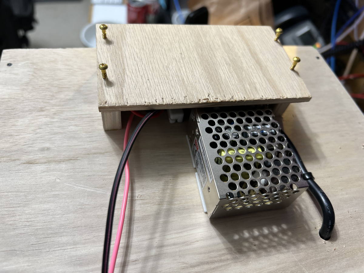
- Secure the Meanwell supply from the bottom (no holes) side against the flat surface of your power shelf (top of nodebox shelf shelf or top of node box)
- Make the AC cord mechanically rigid with respect to the Meanwell supply by securely attaching it to the shelf.
- Secure the bridge rectifier circuit and the DROK regulator device.
- Power on the Meanwell.
- Observe that the DROK supply has lit its LEDs.
- click the right and left buttons on the DROK until tbe numeric display shows the 13.8 V and the right red LED (near the button closest to the output terminals) is on telling you that you are measuring the output voltage.
- Adjust the multi-turn pot closer to the INPUT terminals counterclockwise about 8 turns, maybe.
The voltage won't drop for several turns and then it moves quickly.
Adjust the regulator output voltage to 5.2 V (as measured using the USB Voltage Tester or using a VOM at the OUT screw terminals) or so before plugging in the Raspberry PI.
- Test the battery with the positive lead disconnected and make sure the is at around 12 Volts.
- Turn on the battery connect switch.
- Test the voltages at the battery leads (without the battery in circuit) and adjust the Meanwell so the battery leads are at 13.8 V.
- Turn off the battery connect switch.
- Attach the battery to its leads.
- Turn on the battery connect switch.
- Unplug the Meanwell and verify that the DROK stays lit.
- Replug the Meanwell.
- Attach the USB to the DROK supply and plug in the Raspberry PI.
- Observe the power light on the Raspberry PI.
Wiring AC cord to Meanwell Power Supply
WARNING!!!!
This process needs to be handled very carefully as 110VAC is dangerous.
I am not qualified to describe this at all and I'm completely unfamiliar with the wiring requirements outside the USA.
Please consult local information to determine if you can safely and legally use this kind of power supply.
Even inside the USA, I'm not qualified to do anything like this, much less advise you to do it.
Proceed at your own risk.
Please be prepared to survive screwing up, and then do not screw up.
Check and doublecheck.
|
Route the AC cable in such a way that stress cannot be put on the wires where they connect to the Meanwell, even by pulling the cord at the plug end.
The Meanwell must be solidly attached to the node box and the wires should be strain relieved.
Either drill two holes into the shelf, left and right of the power wire, and then use tie wraps through the hole and around the wire, or drill a hole through the cabinet and run the wire from the outlet, through that hole, and then to the Meanwell.
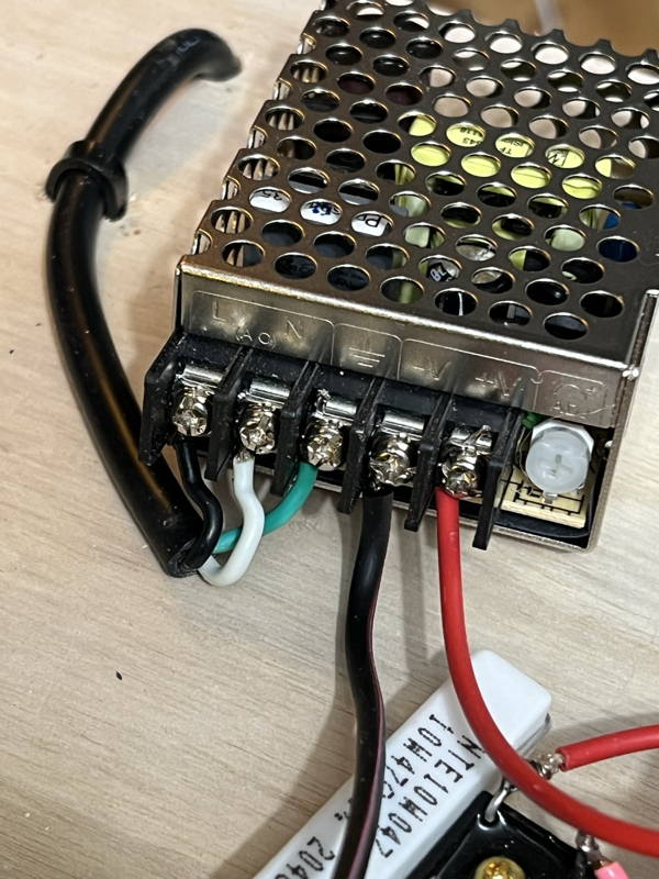
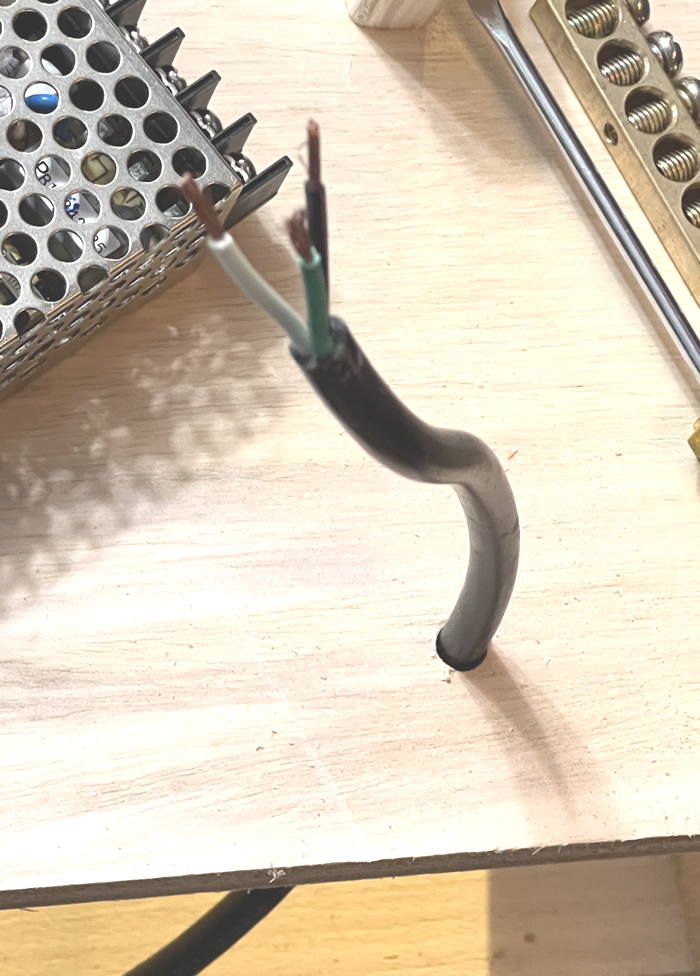 Wiring:
The color codes of the wires are not obvious though they are supposed to be obvious.
While the Wiring-Code that describes safe electrical connections is quite clear about the colors expected in AC power cables in various countries, the color codes are not the same in the different countries.
In the USA, where there is supposed to be one standard, I have found power cables that have correct colors for the European market, and they are not the same as USA colors.
Either way, I don't trust that the colors are wired to the pins they should be wired to.
Wiring Color Codes [allaboutcircuits.com]
Before wiring to the Meanwell supply, use an ohm-meter to verify that the color wires are correctly wired to the plug.
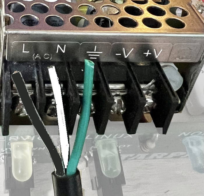
Refer to the 3-prong plug diagram for white, black and green colors.
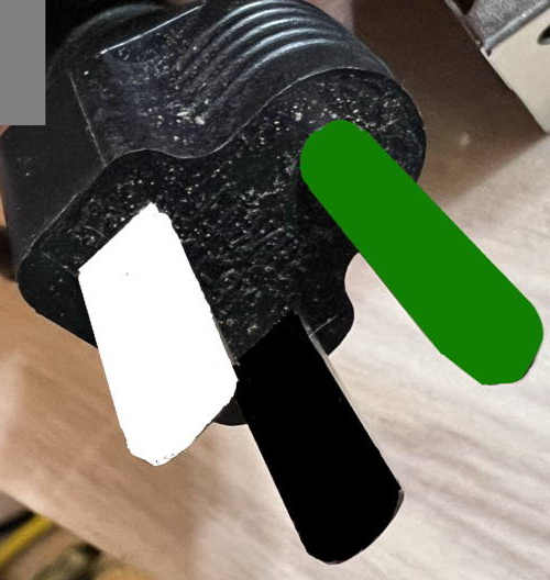
If your cable is appropriate for this task with the proper white, black and green and they are connected to the plug in the USA standard order,
solder tin the 3 wires and hook them up so green goes to

ground, black goes to
L load and white goes to
N neutral.
| WARNING!!!!
Under construction.
|
Adjust the output of the Meanwell while measuring at the orange wire coming out of the diode bridge rectifier.

Build the Robust-Power / Raspberry PI / Control Panel shelf
Components:
- TARPN Control Panel
- (1) DC-DC regulator device with 5.2 V adjustable output like the DROK with USB cable attached.
- (1) Raspberry PI whose power connector matches the USB coming off of the regulator.
- (1) 3d printed NinoTNC mounting plate.
- (4) M3x0.5mm thread Hex Nuts - McMaster-Carr 91828A211 - for inserting into the mounting plate.
- (4) M3x0.5mm thead 8mm long machine screws - McMaster-Carr 92000A118 - for screwing the Raspberry PI onto the mounting plate
- VELCRO Brand - Sticky Back Hook and Loop Fasteners – 15ft x 3/4in Tape | White - for attaching Raspberry PI to the shelf
- (1) Assembled bridge rectifier and resistor.
- (1) Gel Cel battery
- (1) Meanwell RS-15-15 Specifications [meanwell.com]. Mouser. Digikey.
- 6 or 7 inch short USB cable - Amazon has some 7 inch and .5 foot cables - any length cut down to 6" or so if home-brewing the regulator-output connection
- double face tape for permanently attaching the Meanwell to the top of a shelf within or on the top of your node cabinet.
- 6-foot of hookup wire, 16 to 20 AWG.
Preferably in 4 colors, red, orange, pink, black.
This wire passes at most 1 Amp at 14.2 VDC
- (1) 8 position (or more) ground bus. I'm partial to the Square D units.
There are other solutions.
I found a 10-pack of 8-terminal units for $16 on Amazon ASIN = B08PFT5GXJ.
- (2) control panel rails - 1+1/4 inch x 2 inch (or longer) Blondwood (Lowes hardware) plywood blocks
- (1) Raspberry PI shelf - 3 inches by 5+1/4 inches out of 1/4" plywood (Lowes hardware)
- (4) female Crimp-on lugs for the Gel Cel and for the back of the Control Panel.
- (8) 1/2 inch #4 brass phillips decorative rounded head screw for wood - McMaster-Carr 98685A330 - screw Raspberry PI plate to top of Control Panel rails - and mount regulator to shelf
- (4) 3/8 inch #4 brass phillips decorative rounded head screw for wood - McMaster-Carr 98685A540 - screw Control Panel into rails
- (4) insulating spacers.
Possibly McMaster-Carr 90089A305 (100) for $2.62 to space the regulator off the shelf.
- (?) 3 to 6 inch tie wraps.
- (?) Fancy adhesive clips to grab wires and hold them in place.
Fancy!
Instead you could drill holes in the shelf and use tie wraps.
Tools
- (2) 2 inch jaw spring loaded clamps
- (3) 2 inch openning C clamps
- Sacrificial scissors for cutting gooey Velcro
- Soldering equipment for tinning wires
- 3/8 inch heat shrink and heat gun
- (1) 8 inch square
- small, medium and big flat-head screwdrivers.
- small, medium and big Phillips-head screwdrivers.
- 4.5" needle nosed pliers
- 6" slip joint pliers
- 4" diagonal cutters
- Volt-Ohm-Meter
- 1/16th inch drill bit
- 1/4 inch drill bit
- speed drill
- soldering iron (could be station or gun)
- lug crimpers
- wire strippers
- knife for stripping wire
- (4) extra wooden blocks out of the thicker plywood
- Tight Bond II or equivalent wood glue
- Paper towel for cleaning clue off your hands
- rectangular wood pieces for use as chocks during construction
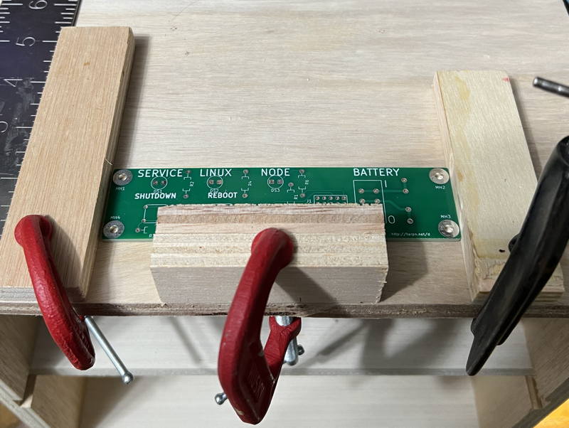
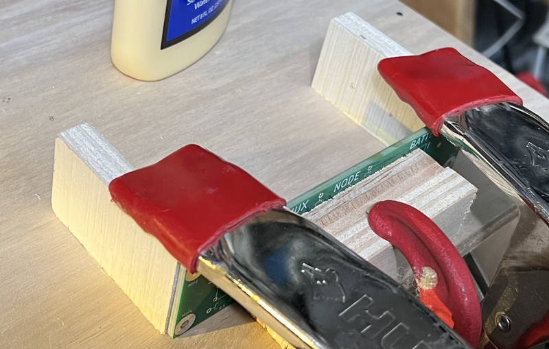
Using some extra wood blocks (chocks), I space the control back from the edge so the buttons are less likely to get broken.
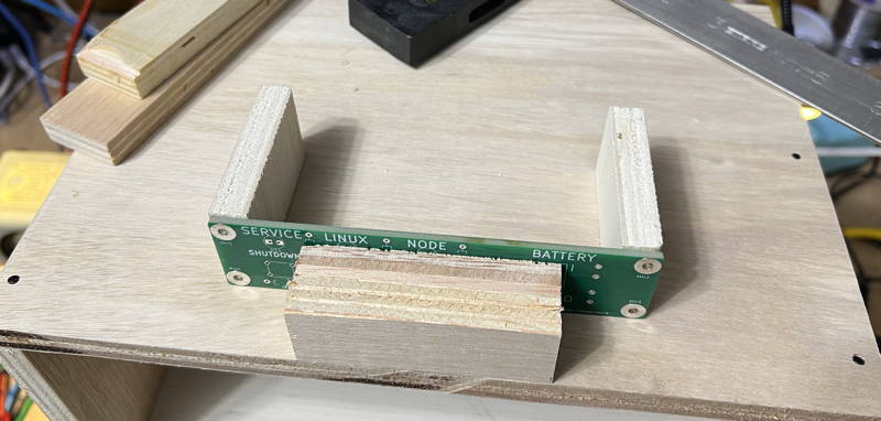
Your purpose is to glue two front-to-back rails into place and mount the control panel to those pieces using wood screws.
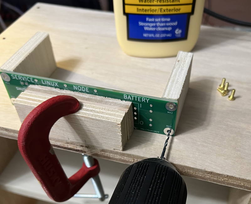
First, make it easy to get the control panel rails into the desired location by putting guidance blocks ("chocks") to the left and right of the control panel mount rails..
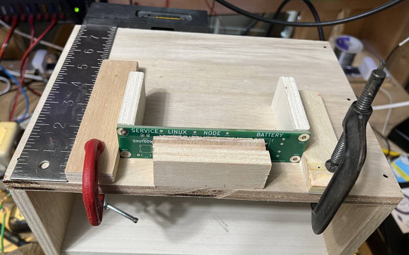
Clamp the front chock as well so it is easy to position the control panel and the two pieces of wood.
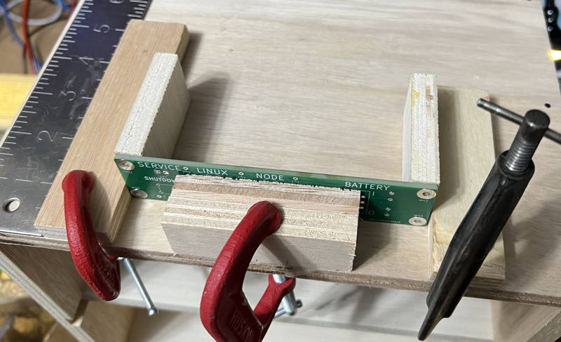
All the chocks are now easy to place.
Test fit the control panel and the two pieces you are gluing.
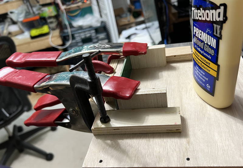
Put glue on the bottom of the two control panel rails and wipe smooth with a finger.
Immediately clamp the two glued pieces and make sure they are up against the chocks.
Remove the side chocks to reveal glue that spread out from under the two pieces.
Clean up the visible glue with your finger.
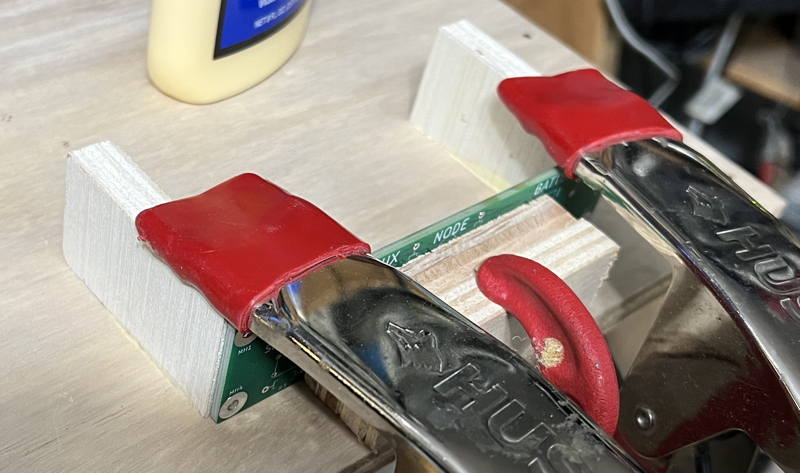
That looks better.
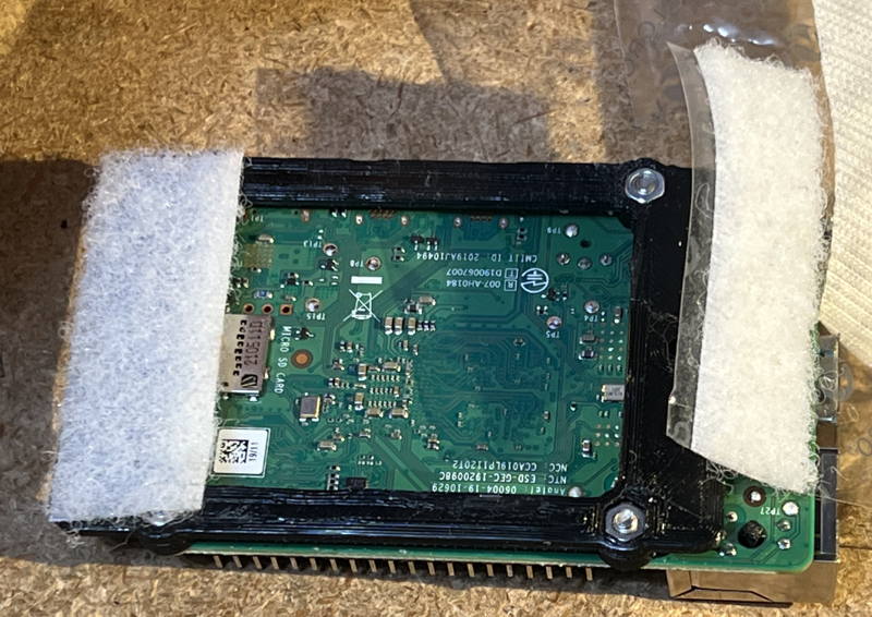
While the glue is drying, find your plastic Raspberry PI plate, velcro, M3 nuts and screws, and the Raspberry PI.
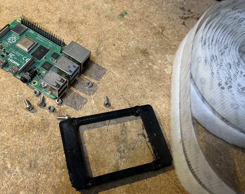
The M3 screw will not fit through the hole in the Raspberry PI
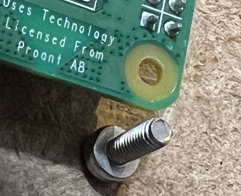
Use the reamer (or drill bit) to enlarge the 4 holes until the screws fit.
This picture shows the desired result.
In order to get this, you first need to press or hammer or squeeze with pliers to press the four nuts into the bottom of the mounting plate.
Try to line up the hex nut with the hex shaped hole in the bottom of the plate, and then squeeze with pliers.
The plates are a little fragile, but they are also cheap.
Cut 2+1/4 inch loop velcro (the soft side) and apply it to the fat portions of the plastic Raspberry PI plate.
Now that an hour has elapsed and the glue has dried:
Using a 1/16 inch drill bit, pre-drill the wood-screw holes for the Control Panel.
Drill a hole that is something less than 1/2 inch deep as close to the center of the mounting hole as you can.
You'll eventually be mounting a finished control panel using 3/8 inch #4 wood screws.
Cut a piece of wood about 3 inches by 5+1/4 inches out of 1/4" plywood.
This will be the Raspberry PI mount and we will use wood screws to attach this to the top of the control panel mount rails.
Assemble the control panel.
Assembly Instructions
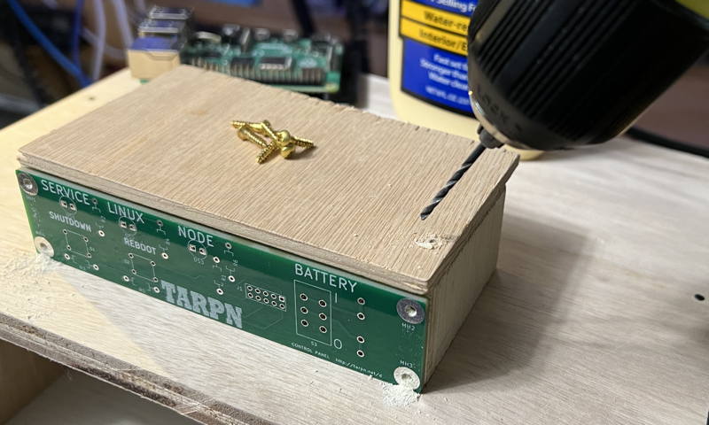
Using a 1/16th inch drill bit, drill 1 starter hole through the Raspberry PI mount into the control panel rail and apply one 1/2 inch #4 wood screw.
Then finish by drilling 3 more holes but don't screw them down yet.
Remove Raspberry PI plate and work on the Meanwell supply and the bridge rectifier switchover/charge circuit.
Place the regulator here.
Run the USB cable over to the Raspberry PI and prove that it reaches.
Pre-drill a hole to secure the regulator using your 1/16th inch drill bit.
Use washers or nylon nuts to space the regulator off the wood and screw the one corner of the regulator down using a 1/2 inch #4 wood screw.
Pre-drill the remaining 3 holes. Loosely secure the opposite corner, again with the spacer of some kind.
Wire the bridge-rectifier output (pink) to the +V input to the regulator and wire a black ground wire to the -V input.
Connect the black ground wire to the ground bus.
Apply power to the Meanwell supply.
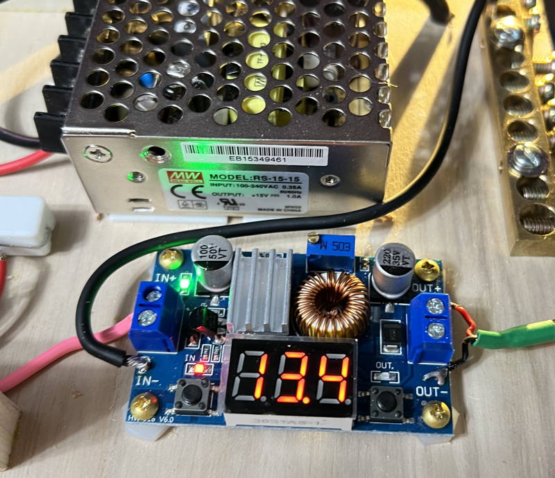
Exercise the two buttons on the regulator.
One button will turn the display on and off.
The other button selects whether you are displaying the INput voltage or the OUTput voltage.
Both voltages should read 13.4 V.
Note: it is 13.4 V because your Meanwell is set to 14.2 V and then there are two diode drops before it reaches the regulator.
Configure the regulator to show the OUT voltage.
Using a small flat head screwdriver, turn the multi-turn pot counterclockwise.
Pay attention to the voltage.
It won't change at all at first.
When you hit the critical range, it moves rather quickly.
That will do.
Now screw down all 4 corners of the regulator using 1/2 inch #4 wood screws and the same spacers you used before.
Place the battery into the side-car with the lugs against the front of the box.
Plus should be up so it is protected against some stray wire touching it under the sidecar.
The lugs should be front so they can't touch the metal HP power supply.
Make a custom length orange jumper with lugs on each end to connect the
+ terminal of the battery to the back of the control panel.
This will connect the battery
+ terminal to the lug on the back of the control panel.
Make a custom length black jumper with lug on one end, and tined wire on the other for connecting the
- (minus) terminal of the battery to the ground bus.
Hook up the wires.
Plug in the Meanwell.
Remove the memory card from the Raspberry PI, if any.
Plug the USB cable into the Raspberry PI.
The lights come on.
If you turn on the battery switch on the control panel, you should be able to unplug the Meanwell and have the regulator and PI stay on.
Screw down the four 1/2 inch #4 wood screws to hold the Raspberry PI shelf to the Control Panel rails.
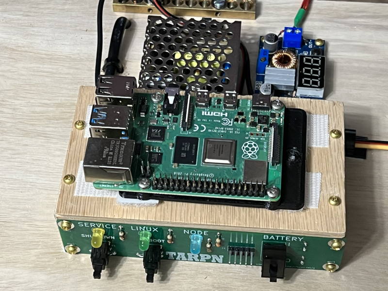
Apply hook Velcro from side to side across the Raspberry PI shelf so it meets the Raspberry PI's vecro toward the front of the shelf (by the Control Panel) and toward the back of the shelf (toward the Meanwell).
Place the Raspberry PI, bracket down, and USB connectors to the left, down on the velcro pad.
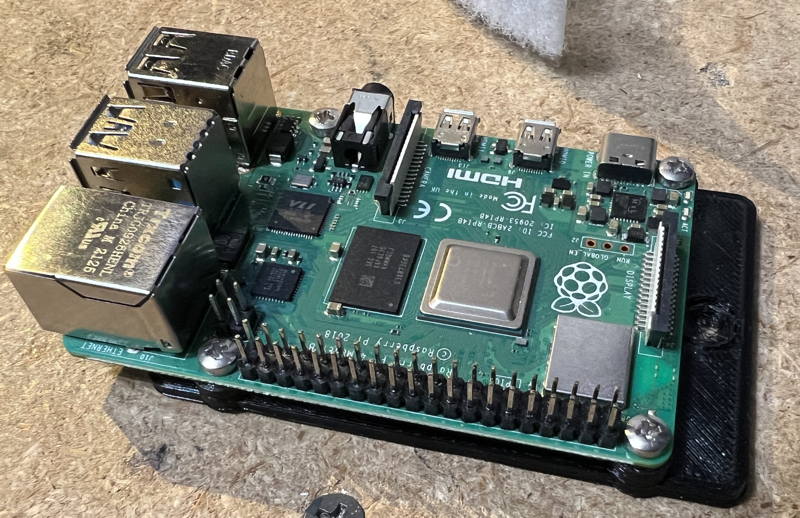
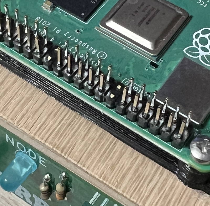
Now we're going to break four pins off of the Raspberry PI's 40-pin auxiliary connector to make room for the 2x5 ribbon cable connector.
There must be space on both sides of the connector.
Row 7, measured from the SDcard end of the Raspberry PI must be removed, as well as row 13.
See the next several images for the steps I use to do this.
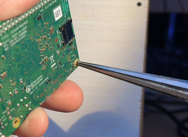
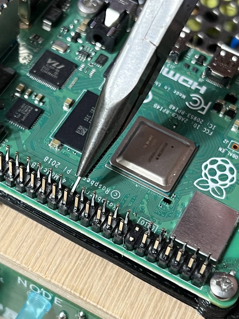
Grab first pin, on row 7.
We'll bend this with a long nose plier.
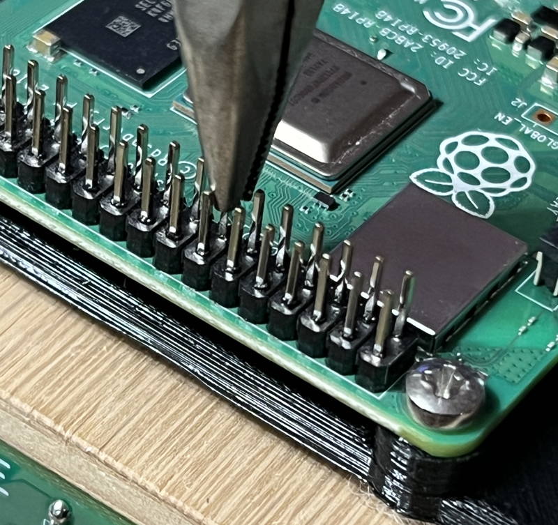
You'll need to wiggle the pin toward the CPU and then straight back up, and repeat several times.
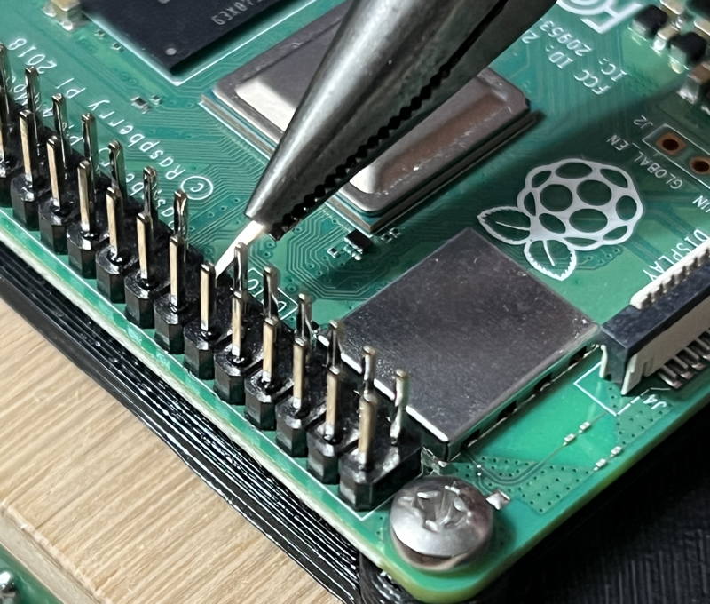
7th row now removed
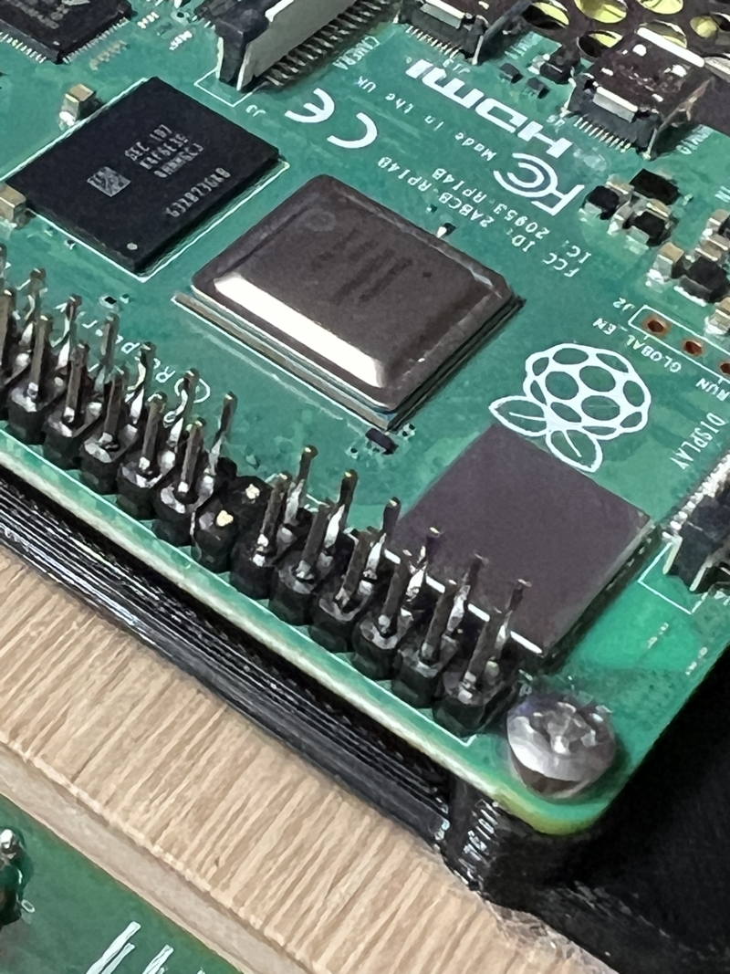
On the 13rd row, break both pins
You can see in this image there is now room for a 2x5 header, in the middle of the Aux connector.
Cut a 4 inch piece of ribbon cable.
Crmip IDC connector on each end of the ribbon cable such that the IDC connectors are separated by 2.5 inches with an inch of spare on each side.
Make sure they are square to the ribbon cable.
Eyeballing it should be sufficient.
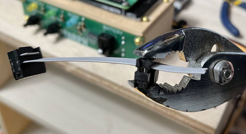
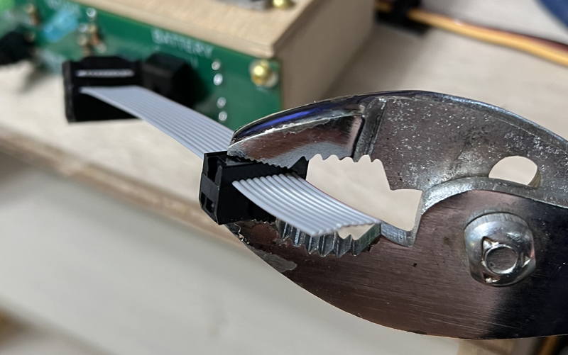
If you have enough extra on the ends, wrap it around the connector and install the straign relief part of the IDC connector.
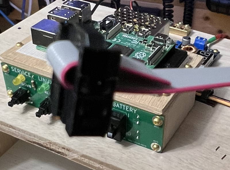
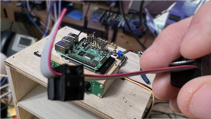
Attach ribbon cable to control panel and Raspberry PI as shown
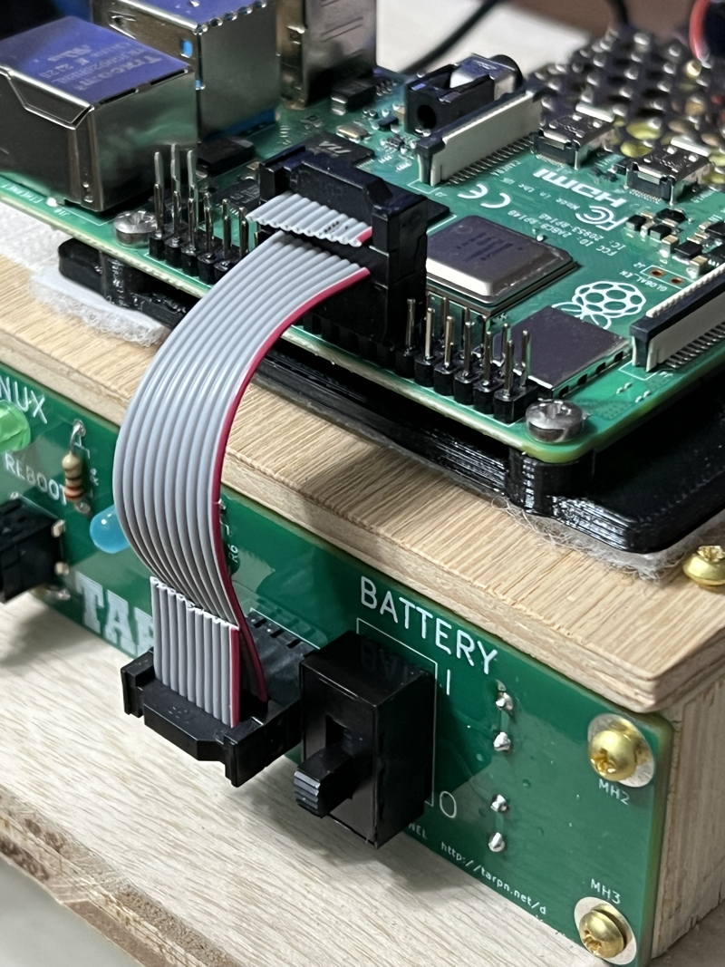
Your Raspberry PI shelf is complete.
If you have an SDCard node already built, you can power it up and see the control panel light up.
Otherwise,
initialize your Raspberry PI to be a TARPN Node.