| home | builders |
| builders ➜ Cabinetry ➜ Box7 - 2018 Node Mod-Box |
|
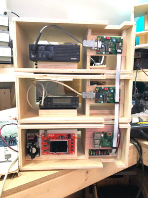
The system consists of a base box and one or more radio boxes.
Each base box has support for
Each radio box has support for
|
|
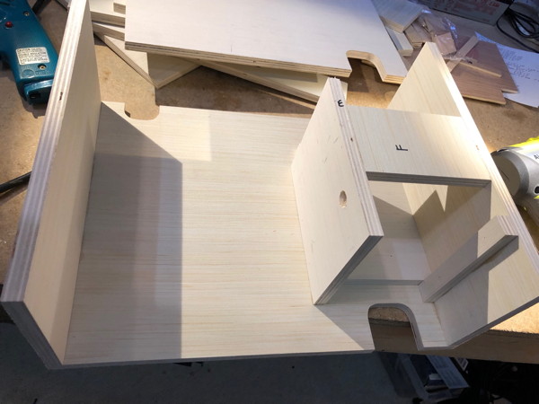
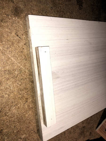
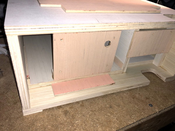
| Left chassis and Slide In Pan | The Left chassis is 8-1/2″ wide. The primary feature of the left chassis is an 8-1/2″ wide slide-in pan which is of one of two depths. The slide-in pan is placed into the left chassis from the rear and is slid up under the rails until it strikes the front-pan-stopper. For the radio version of the mod box, the radio-pan is 3″ deep and has a radio-block on top onto which a radio is Velcroed. For the Base-Box version of the mod box, the o-scope-pan is 9″ deep and has a plate in the front onto which the DSO138 oscilloscope is mounted. The 9″ o-scope-pan is perfect for mounting power supplies, fuse distribution, and other peripherals. Both pans are removable and are held in by Velcroed accessories located toward the rear of the box, and which keep the pan from sliding backwards. | 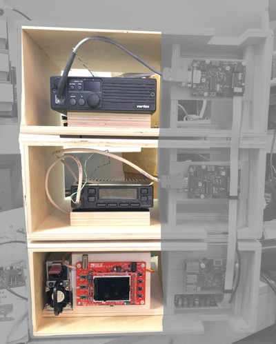 |
| Right chassis | The Right chassis is 4-3/4″ wide. On the front of the box a plate presents the Raspberry PI or a TNC-PI. The ribbon cable from these units goes up and down the stack of boxes through a cut notch in the front top and bottom edges of the box. The cable from the TNC-PI to the radio exits to the left across the front of the radio box. A ribbon cable runs up and down from the Raspberry PI to each of the TNC-PI. The plate for mounting the board is across the middle of the space leaving room above and below for both airflow, and access for running wires to the Raspberry PI and to the PWRMAN board which may be plugged into the Raspberry PI as a daughter/shield card. A fan may be located near the rear of the right chassis, blowing forward. If the mod box was placed against a wall blocking the rear, the Center Divider would permit air blown through the fan to be drawn over the radio or power supply, providing excellent cooling. | 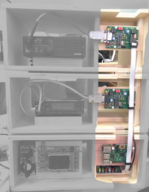 |
| Center-divider | A structural member is located between the left and right chassis and runs from near the front of the mod-box to near the rear. The center-divider serves as a mount for the Raspberry PI/TNC-PI plate, as structure to hold the roof of the box up, and also as an air-flow guide. | 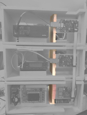 |
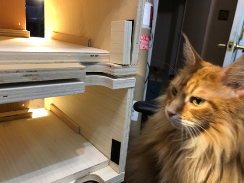
| Top Panel | This is a rectangular piece of 3/16" plywood on top of each box. The box which sits above this Top Panel will fit perfectly such that it won't slide off. The footpads on the bottom of each box fit perfectly around the Top Panel of the box below. We may be able to get the TARPN logo etched into the Top Panel which will look really great. | 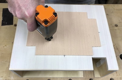
 |
| 15 pieces of 1/2″ plywood | |||
|---|---|---|---|
| A | Box-Roof | 14-3/4″ wide x 11-3/4″ deep |
The Box-Roof and Box-Bottom parts are nearly identical.
Both parts have marks to assist in placement of the Top-Panel (P). In the case of the Box Bottom, the marks are for temporary placement of the Top-Panel to aid in proper placement of the Footpads (Q). |
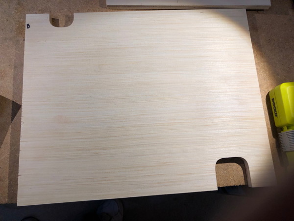
| B | Box-Bottom | 14-3/4″ wide x 11-3/4″ deep | The difference between Box-Bottom and Box-Roof are that the notches are on opposite ends of the piece relative to the lighter-side and darker-side. Box-Bottom has the bigger notch on the right if the white-side is down. Box-Roof has the notch on the right if the white-site is up. |
| C | Box-Right-Side | 5-1/4″ high x 11-3/4″ deep | The Box-Right-Side and Box-Left-Side parts are identical. |
| D | Box-Left-Side | 5-1/4″ high x 11-3/4″ deep | The Box-Right-Side and Box-Left-Side sit on the box-bottom. |
| E | Center-Support | 5-1/4″ high x 6-3/4″ deep | Center-Support runs front to back near the middle of the box. A drill spot is marked on this board. Later during one of the assembly steps you'll be asked to drill out this spot. |
| F | Ceiling-Brace | 4-3/4″ wide x 3″ deep | Across the top of the right side of the box. This is used to enforce the spacing between Center-Support and Box-Right-Side |
| G | Floor-Brace | 4-3/4″ wide x 7″ deep | Across the bottom of the right side of the box. This is used to enforce the spacing between Center-Support and Box-Right-Side |
| H | Front-Right-Panel-Brace | 5-1/4″ high x 3/4″ deep | This supports the right hand side of the Circuit-Board-Panel |
| I | O-Scope-Panel-Brace | 5-1/4″ wide x 3/4″ deep | This piece adds structure to the Scope-Panel where it glues to the O-Scope-Pan |
| J | O-Scope-Pan | 8-1/2″ wide x 9″ deep | This piece supports the DSO138 oscilloscope, main power supply, fuse block, and other peripherals. The pan slides into the left side of the box from the rear. |
| K | Back-Pan-Stopper | 2″ high x 1″ deep | |
| L | Radio-Block | 5-1/4″ wide x 3″ deep | Velcro on top of this piece holds down the front of the radio. |
| M | Radio-Pan | 8-1/2″ wide x 3″ deep | This piece supports the Radio-Block. The pan slides into the left side of the box from the rear. |
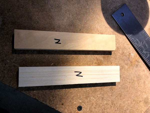
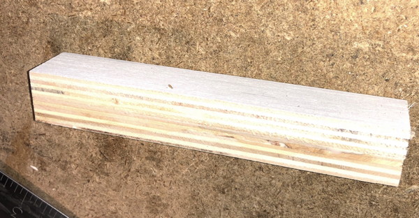
| N | Rear-Radio-Support 2 of these | 1″ wide x 6″ deep | These pieces get glued together and are used to support the back of the radio under the heat sink. |
| 14 pieces of 3/16″ plywood | |||
|---|---|---|---|
| O | Circuit-Board-Panel | 5-1/4″ wide x 2-1/2″ high | The Raspberry PI or TNC-PI mounts to this panel. Four spots are marked on this panel which will be drilled out in an assembly step. |
| P | Top-Panel | 10-3/4″ wide x 7-3/4″ deep |
This odd shaped piece sits on top of the mod-box and if another mod-box is placed on top of this one, the feet fit around this pattern perfectly.
This piece is marked on the edges to match the marks on the Box-Roof (A). |
| Q | Footpads, 8 of them | 1-1/4″ x 1-1/4″ | These are on the bottom of the box. Four are in the corners of the bottom, and four are located so they exactly fit on the outside of the top-panel for the mod-box this box is sitting on top of. |
| R | Interior-Pan-Rail, 2 of them | 1/2″ high x 6″ deep | These secure the O-Scope-Pan or Radio-Pan so it won't rock up or fall out when the box is moved or bumped. The pan slides under these rails. |
| S | Front-Pan-Stopper | 5-1/4″ wide x 1-1/4″ deep | This piece blocks the pan from sliding out the front of the box. It could also be a good place to put a label or sticker or maybe the wood could be etched with the node-name or the name of the neighbor node this radio talks to? |
| T | Scope-Panel | 5-14″ wide x 4″ high | The DSO138 scope mounts to this panel. Five holes are marked in this panel which will be drilled out during one of the assembly steps. |
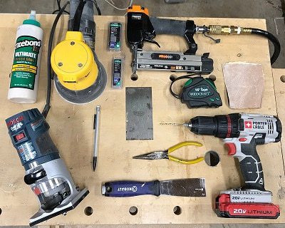
| Hardware and Glue (not included with kit) | ||
|---|---|---|
| TiteBond III glue or equivalent (may be called ″TiteBond III Ultimate″) | ||
| < 100 | 3/4″ 23 gauge pin nails | |
| < 100 | 1/2″ 23 gauge pin nails | |
| Base-Box hardware | ||
| (8) | 3/8″ 4-40 standoffs | For all hardware, zinc plated brass is cheap and adaquate |
| (8) | 1/2″ 4-40 screws | |
| (8) | 4-40 nuts | |
| Radio-Box hardware | ||
| (4) | 3/8″ 4-40 standoffs | |
| (4) | 1/2″ 4-40 screws | |
| (4) | 4-40 nuts | |
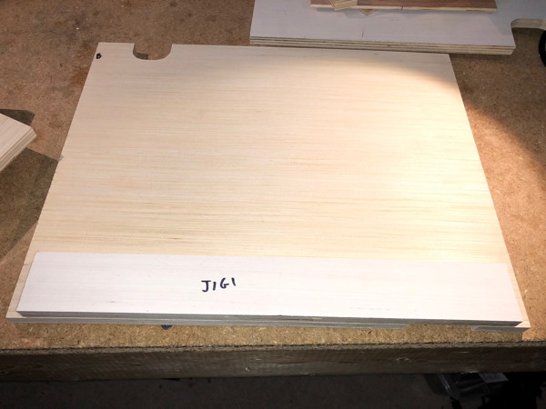
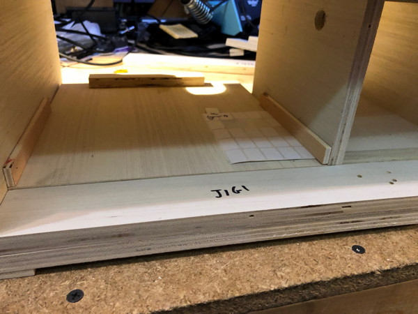
| #1 | Front-Edge-Jig | 13-3/4″ x 1-3/4″ | Used in placement of the forward edge of the pans and the Center-Support as well as to simplify placements of the Box-Left-Side and Box-Right-Side. |
| #2 | Back-Edge-Jig | 13-3/4″ x 1-3/4″ | Used to enforce the placement of the sides of the box and for sanity testing the Floor-Brace. |
| #3 | Board-panel-sizer-Jig | 6″ x 7/8″ | Used in placement of the Circuit-Board-Panel (which holds the TNC-PI or Raspberry PI) |
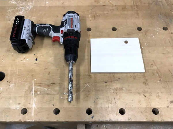
| 1 | Find Center-Support (E). Drill a 1/2″ hole through the Center-Support (E) where marked. This is a wire pass-thru hole.. |
|
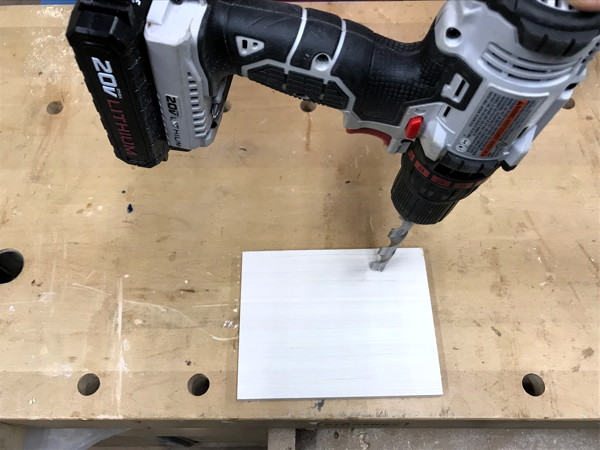
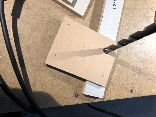
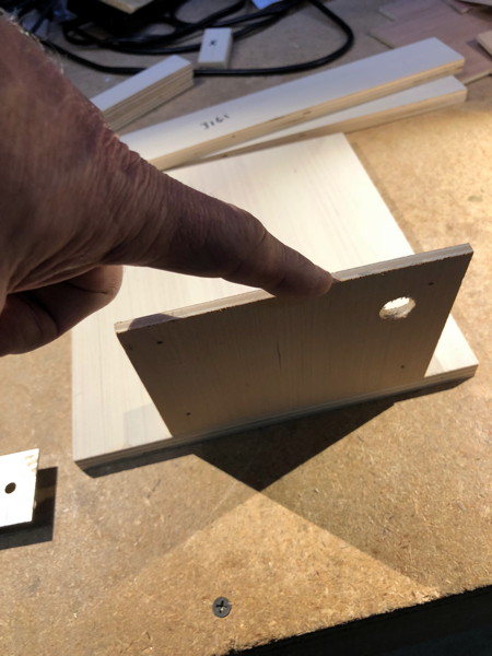
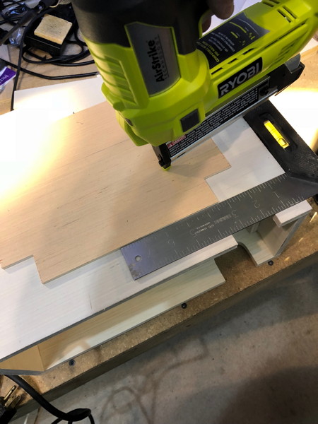
| 2 | Find the Scope-Panel (T). Drill a 1/2″ hole through the Scope-Panel where marked. It would be better if you placed the Scope-Panel over a piece of scrap wood (you can use one end of Jig 1) so the hole comes through neater. |
|
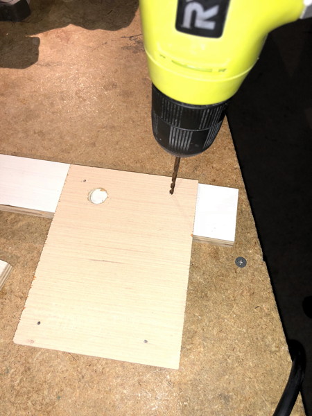
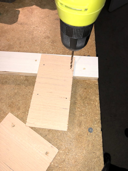
| 3 | Drill four 1/8″ hole through the Scope-Panel where marked. |
|
| 4 |
Locate Circuit-Board-Panel (O).
Drill four 1/8″ hole through the Circuit-Board-Panel where marked. |
|
| 1 | Place Box-Bottom (b) on your table such that the white-side of the board is down and the larger of the two notches is facing forward. |
|
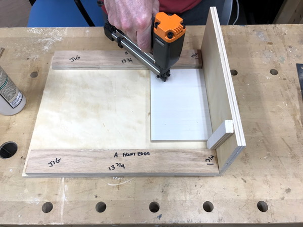
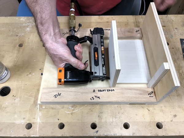
| 2 | Place Front-Edge-Jig (#1) on the front edge of the Box-Bottom so it is flush with the front edge and centered along that front edge. |
|
| 3 | Place Back-Edge-Jig (#2) on the back edge of the Box-Bottom so it is flush with the back edge and centered along that back edge. | |
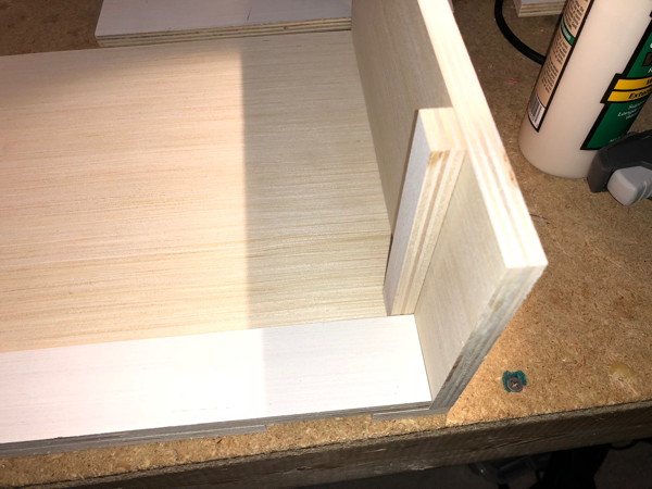
| 4 | Locate Front-Right-Panel-Brace (H), Box-Right-Side (C), Floor-Brace (G).
Note that the pieces marked H and I can be confused since a sideways H looks like an I. However, the two pieces are the same size so it just doesn't matter. In this step we're going to glue and pin Floor-Brace to Box-Bottom. Temporarily place Box-Right-Side as shown with white-side facing out-right. Temporarily place Front-Right-Panel-Brace with white-side facing left, and up against Box-Right-Side as shown. The two pieces, brace and side, are sitting on the right edge of Box-Bottom. Run your finger up the right edge, front and back and make sure the Jig and Box-Right-Side are perfectly placed. Note that when the parts are placed, the lettering (H), (C) and (G) are not visible. Now glue and pin Floor-Brace (G) to the bottom such that it is immediately behind the Front-Right-Panel-Brace, making sure not to impact the placement of the Box-Right-Side and making sure the glue goes on the not-white side of Floor Brace (G). |
|
| 5 | Glue and pin the Front-Right-Panel-Brace (H) into the inside Box-Right-Side (C).
Note: The Front-Right-Panel-Brace wiggles as you compress it into the side. Also note that the Floor-Brace and Jig have very straight edges. Squeezing the Jig against the Front-Right-Panel-Brace will keep it straight and then move to push down on the Front-Right-Panel-Brace. |
 |
| 6 | Temporarily put the Center-Support (E) in place nudged forward to the Front-Edge-Jig and against the Floor-Brace. See that the hole you drilled earlier is up and forward. Put glue on the bottom and bottom-right edge of the Center-Support and place it into the box up against the Front-Edge-Jig as shown. Pin the Center-Support on the left side, into the Floor-Brace. Remove the Front-Jig and wipe away any glue that gets loose. |
 |
| 7 | Move the Box-Right-Side and Front-Right-Panel-Brace assembly out of the way. Apply glue in on the Box-Bottom on the right edge of the Bottom-Brace and in the top of the Box-Bottom where the Box-Right-Side will sit, then put the Box-Right-Side into place. Note that the Floor-Brace will make it easy to place the Box-Right-Side correctly. Pin into the Box-Bottom through the Box-Right-Side bottom edge as shown. Wipe away any excess glue including under the Jigs if they are still in place. |
 |
| 8 |
The Ceiling-Brace (F) will be placed, white side down, in between the Center-Support and the Box-Right-Side, even with the top of each board, and will be located somewhere behind the front-right support.
The front to back position is not so important.
Make sure the Ceiling-Brace ends up even with the top of the Center and Right Side!!! Glue and pin the Ceiling-Brace (F) on both left and right. Wipe away excess glue. |
|
| 9 | Pin the Box-Right-Side in from the bottom. |
|
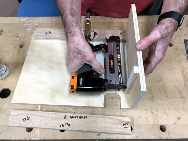
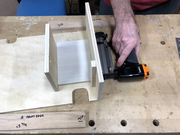
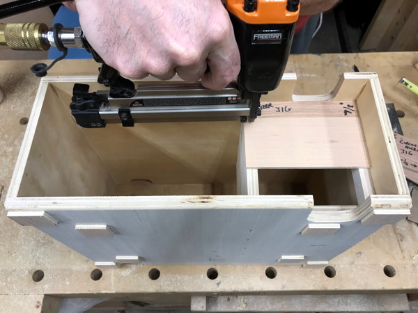
| 10 | Locate Radio-Pan (M) and Box-Left-Side (d). Without gluing yet, place Box-Left-Side in place on top of the left end of Box-Bottom. The white side should be facing out. Take Radio-Pan and with it's wide direction running left and right and fit it between Center-Support and Box-Left-Side. It should barely fit. While keeping Box-Left-Side in place, move the Radio-Pan back and forth and make sure it fits. Your goal is to glue and pin Box-Left-Side in place such that Radio-Pan does not bind and will still fit. Place the front and back jigs along the front and back edges and put the Radio Pan (M) against the Center-Support. Again place Box-Left-Side and hold it on the bottom edge against the jigs and Radio-Pan. Stand the box up on most of the way onto its right side, watching that your loose parts don't come out. Put the box back down. Put glue on a long edge of Box-Left-Side and put it in place on Box-Bottom. Again stand the box up partially and turn it so you can get access to the bottom. Force the bottom of Box-Left-Side against the loose parts to make it be true (90degrees) from the bottom. Use your nailer to pin through the bottom into the Box-Left-Side once near the front of the box and once near the back. Now flip the box on its back and while pushing hard on the bottom over the Box-Left-Side, put several more nails in. If either of your first two nails are pushed partly out, hit them lightly with a hammer. Turn the Box back over with front facing you as before. Using the Radio-Pan as a square, force the Box-Left-Side to be true. Remove the Jigs and wipe away any excess glue. |
|
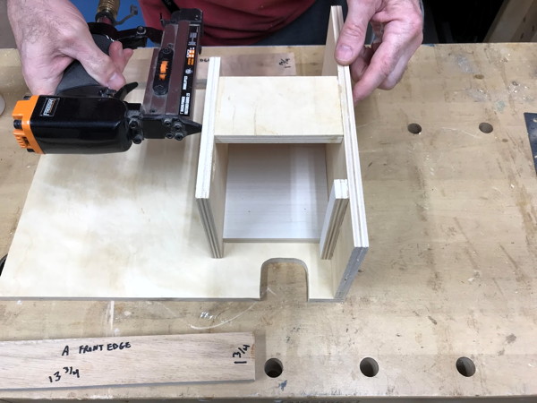
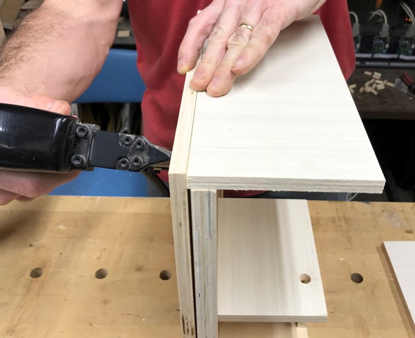
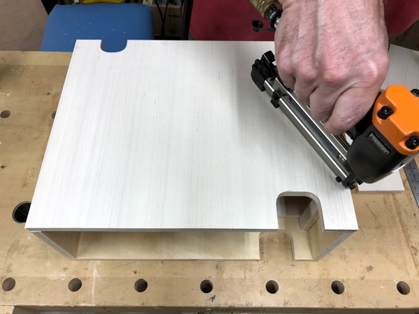
| 11 | Apply glue to all surfaces facing up and then place the Box-Roof (A), white side up and with the larger notch facing forward. |
|
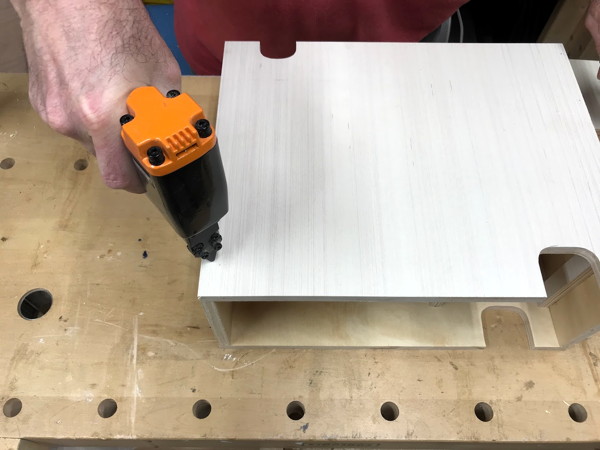
| 12 | Pin the Box-Roof (A) on both top edges while putting pressure on at the points being pinned. |
|
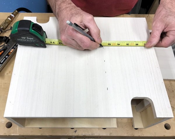
| 13 | Measure 5-1/2″ from the Box-Right-Side on both top and bottom of the box. This marks the location of the Center-Support. |
|
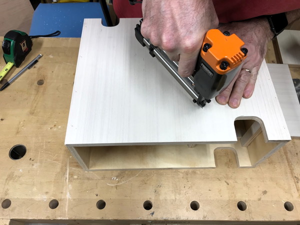
| 14 | Press down on the Box-Top over the Center-Support and pin the Center-Support from the top.
Make sure to pin only into the Center-Support keeping in mind that that support only 6-3/4″ of the total 11-3/4″ length of the box. |
|
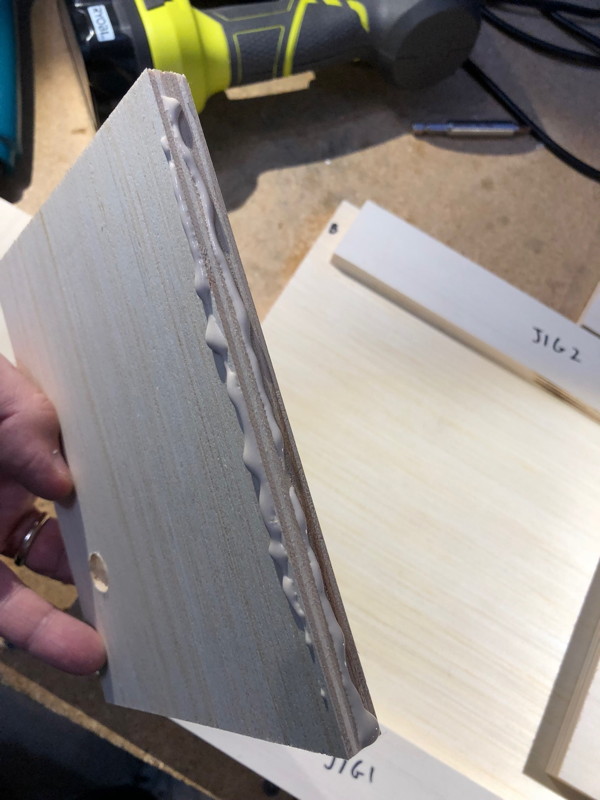
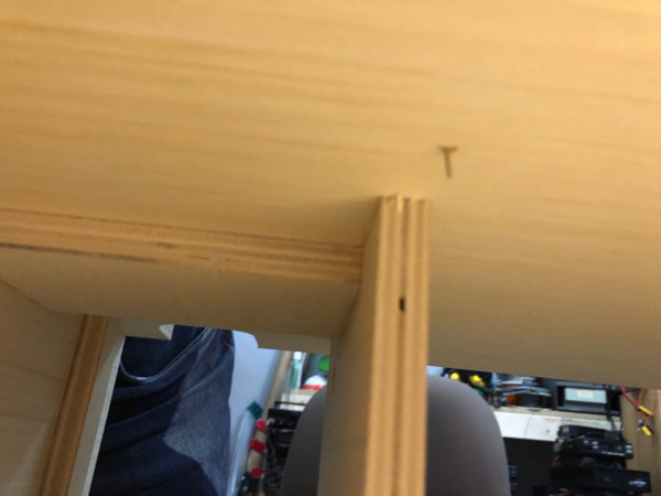
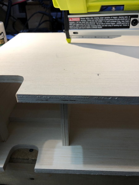
| This is what a miss looks like. To fix a miss, grab the tip of the pin with your long-nose plier and then rotate, wrapping the pin around the plier. Eventually this will pull the nail through the wound. |
| |
|---|---|---|
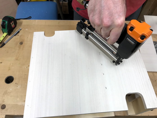
| 15 | Press down on the Box-Top near the Ceiling-Brace and pin above the Ceiling-Brace. |
|
| 16 | Turn the box over and pin into the Center-Support from the bottom of the box. |
|
| 17 |
Inspect the inside of the box looking for spinters and protruding pins.
Site down the corners of the box from front-to-back and look for pins.
If there are any you'll need to take action to fix this lest damage or injury occur.
Pins extending into the bottom of the left part of the box will block proper sliding of the O-Scope-Pan and Radio-Pan. Use the long nose pliers to grab the tip of the pin and then roll the pliers to pull it into the box and remove. | |
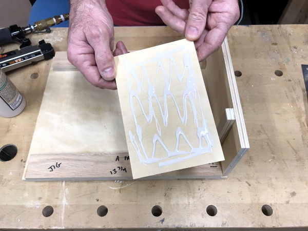
| 18 | Now put the box aside and clear some space.
Find the O-Scope-Pan (J), the O-Scope-Panel-Brace (I), and the Scope-Panel (T).
In this step we're going to glue the O-Scope-Panel-Brace to the O-Scope-Pan.
The O-Scope-Pan is only half an inch deeper than it is wide.
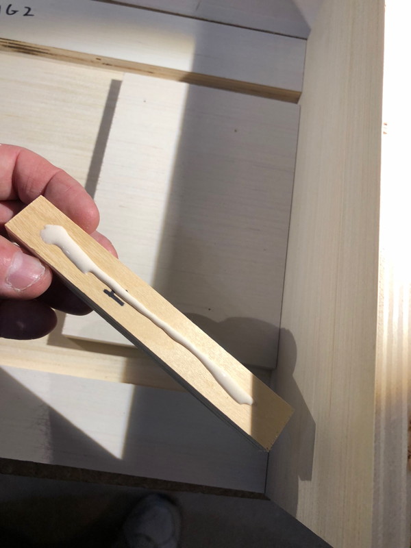
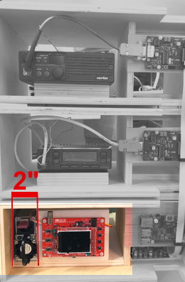
Place the O-Scope-Pan, white side up, with the narrow side (front) facing you. Align the Scope-Panel along the front edge of the O-Scope-Pan 2″ inches away from the left edge of the pan. This 2" space allows the HP DPS1200FB to fit so the supply's fan can exhaust to the front. Place the O-Scope-Panel-Brace behind the Scope-Panel. Glue the O-Scope-Panel-Brace to the O-Scope-Pan and pin through the O-Scope-Panel-Brace from the top but do NOT glue or pin to the thin Scope-Panel. Clean up the excess glue. This is important. Make sure you get the glue off the bottom of the Scope-Panel and out of the area the Scope-Panel will glue into. We're not ready to glue the Scope Panel yet as it requires shorter pin nails. Then put this assembly and the loose Scope-Panel asside for the moment. |
|
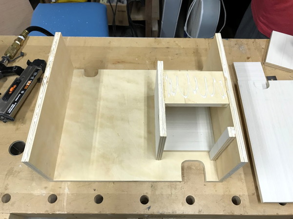
| 19 | Locate Radio-Pan (M) used in a previous step and Radio-Block (L).
Center the Radio-Block, white side up, on top of the Radio-Pan, also white side up. Apply glue to the bottom of the Radio-Block and place it in the middle of the Radio-Pan white-side. Pin the Radio-Block from the top. |
|
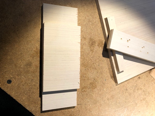
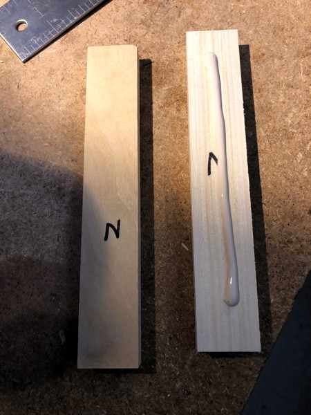
| 20 | Locate the two Rear-Radio-Support (N) pieces.
Apply glue to the non-white side of one Rear-Radio-Support and place it on the non-white side of the other Rear-Radio-Support. Pin the two pieces together. Put this assembly asside for later. |
|
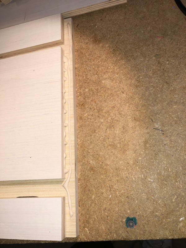
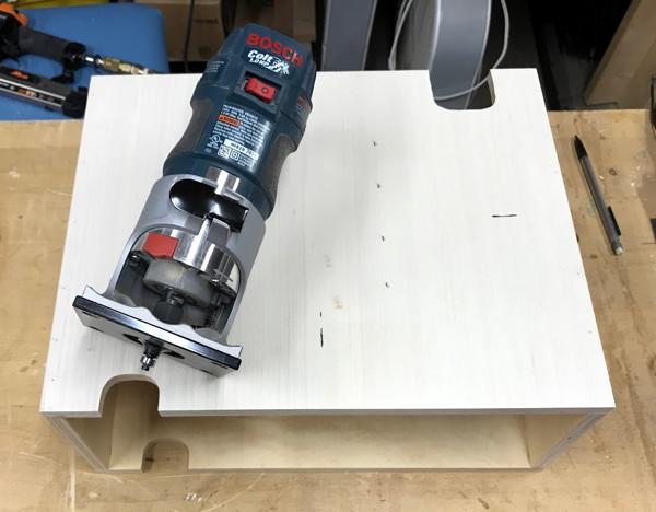
| 1 | Use the handheld router with 1/4″ rounding overbit to round all outer edges.
Exclude the inside of the slots |
|
| 2 | Use Sander and Sandpaper and, at your discretion, sand all surfaces and edges |

|
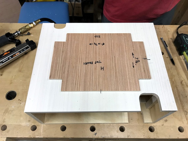
| 1 | Find the Top-Panel (P).
Place the box back on the bench upside down but facing front. The larger slot is on the left-front. With high precision, place the Top-Panel on the box bottom and line up the lines on both panel and box bottom. This will require setting the light side of the Top-Panel up and the letter (P) is facing down. Don't lick the Top-Panel at this time. |
|
| 2 | Use a tape measure to make sure the Top-Panel is exactly in the middle and square front to back and side to side. | |
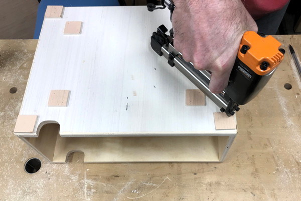
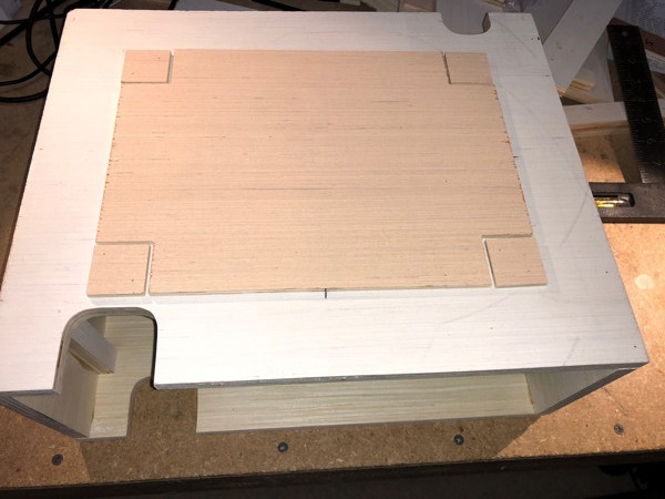
| 3 | Place the four inner Footpads (Q) 1/16" away from the notches on the top panel. |
|
| 4 | Pin each inner Footpad | |
| 5 | Place the 4 outer Footpads on each box bottom corner and pin in place. |
|
| 6 | Place the Top-Panel on the box top and line up the lines on both panel and box top. | |
| 7 | Use a tape measure to make sure the Top-Panel is exactly in the middle and square front to back and side to side.
Pin the Top-Panel in place |
|
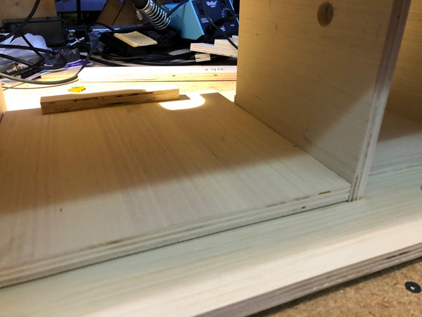
| 1 | Place the O-Scope-Pan in the box left-hand cavity such that the O-Scope-Brace-Panel is to the back. |
|
| 2 | Place the Front-Edge-Jig along the front of the box. Line the Jig up flush with the Box-Bottom front edge. |
|
| 3 | Place a thick piece of paper or two pieces of paper on the left edge of the O-Scope-Pan against the left wall.
Place an Interior-Pan-Rail (R) on the left side and let it rest gently on the paper.
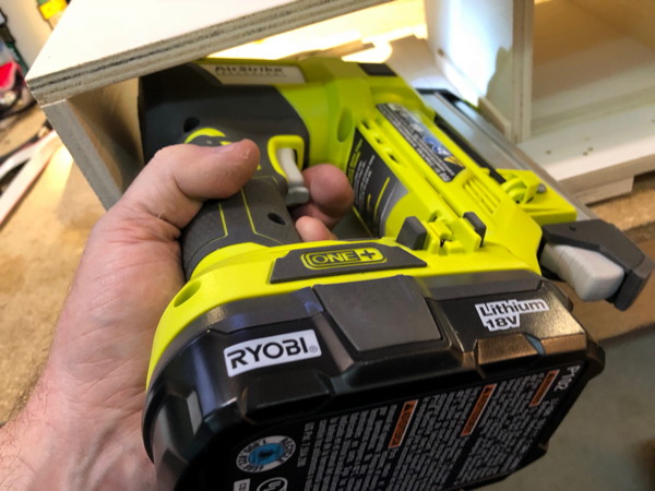
The front end of the rail should be equal with the front of the O-Scope-Pan. Pin the left Interior-Pan-Rail in place. DO NOT GLUE!! You should manage to pin it twice. With my Ryobi nailer, it was tight. |
|
| 5 | Perform step 3 on the right side of the O-Scope-Pan. |
|
| 1 | Turn the box on it’s back (the large slots are UP) Place the Board-Panel-Sizer-Jig (#3)(7/8″ tall) on the top edge of the panel area. Place the Circuit-Board-Panel (O) below the jig. The four holes are mostly to the right. The Circuit-Board-Panel letter (O) is on the back. Pin the panel in place |
 |
| Put asside the box for a moment. | ||
| 5 | Align the Scope-Panel (T) in front of the Scope Panel support. The large drilled hole has to be in the top right and the letter (T) is on the back. Glue and pin the Scope-Panel from the front. |
|
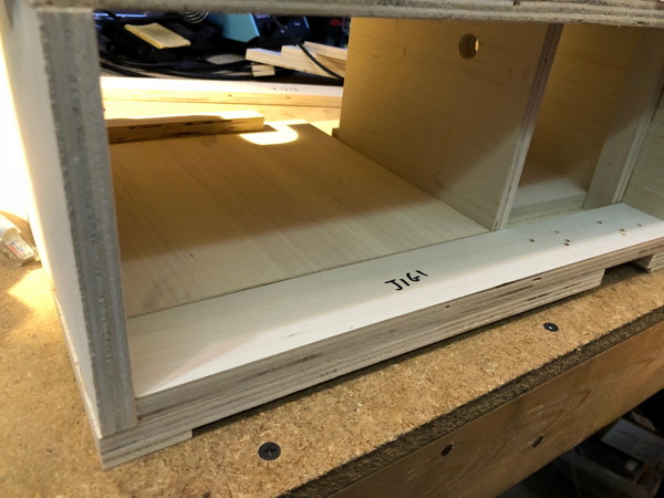
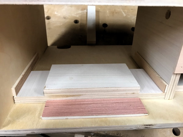
| 6 | Put the box back on the bench upside up and sitting on its bottom.
Insert the O-Scope-Pan in place under the rails and slide it back so the front edge of the pan lines up with the Center-Support. Place the Front-Pan-Stopper (S) in front of the O-Scope-Pan so it is equidistant between the box left and center support. |
|
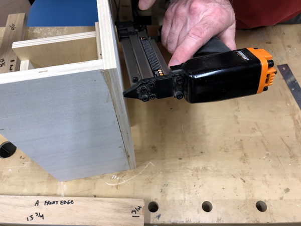
| 9 | Pin the Front Pan Stopper in place. | |
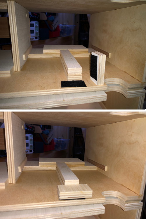
| Now place the Velcro Hooks pad to mate with the Back-Pan-Stopper up on the side of the box, to the left (right if looking into the box from the rear) of the O-Scope Pan. Don't put the velcro on the floor of the box because that will interfere with the pan sliding out. The pic on the right shows two boxes configured with the O-Scope Pan. The upper has the K block Vecroed in place. The lower just shows the Velcro hooks. You can see how the K block would keep the Pan from sliding backwards. |
|
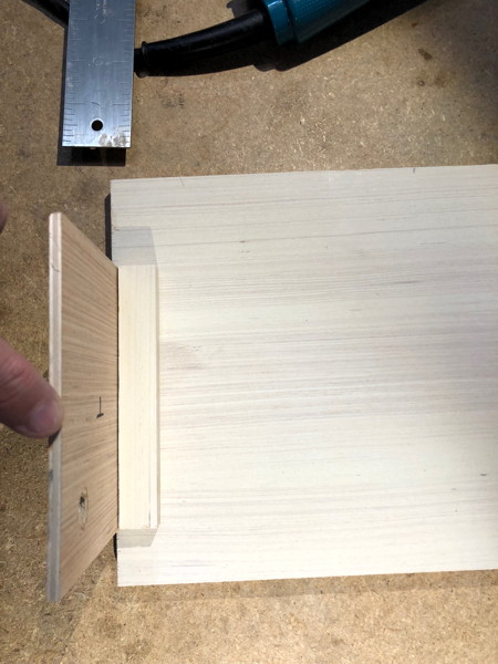
If you are going to use this box as a radio box, slide the O-Scope Pan out of the box from the rear and insert the Radio Pan assembly.
| Slide the Pan assembly up to the front of the box as shown to the right. |
|
| Now turn the box around and place the Rear-Radio-Support assembly behind the Radio Pan. Velcro the K block behind the Rear-Radio-Support assembly as shown in the pic to the right. Put Velcro hooks on the Radio Block with a small amount of overlap onto the Rear-Radio-Support to secure the support in place. Apply Velcro loops on the radio itself. I wouldn't put the Velcro on the radio heatsync as that would reduce heat flow. |
|