See also:
Control Panel/Raspberry PI Shelf
See also:
5.2 V Regulator
See also:
Purchasing and wiring a Meanwell RS-15-15
See also:
Assembling the Switchover Circuit
Robust Power for Raspberry PI
This page discusses a very inexpensive system for using a Sealed Lead Acid (SLA) battery to provide stable power to the Digital Section of a TARPN node.
This involves creating a UPS (Uninteruptable Power Supply) for the Raspberry PI.
Having this diode-switched UPS increases the mean-time between SDcard corruption-caused-app-failures, from months to years.
The Control Panel/Raspberry PI Shelf page goes through a step by step instruction for building the Raspberry PI and Control panel shelf, including the robust power supply.
Before deciding to build your system, please review the pages in the TARPN Raspberry-Pi-Shelf series linked from this page.
Low cost power switchover device
Total parts cost is about $50 at retail if you have to buy a $20 Sealed Lead Acid (SLA) battery.
I have been able to buy the SLA battery for $120 for 10 of them using Amazon.
Perhaps you can replace the SLA battery in one of your UPSs and use it's old battery for this circuit.
This schematic at the bottom of this page shows a simple battery floater circuit and switchover to power a USB power supply.
The purpose of this is to keep the Raspberry PI up through power drop-outs and while moving the network cabinet.
A 2.5 amp gel cell should run the raspberry PI for several hours.
Most of the drop-outs that hurt us are very short, and possibly not noticed.
With the trickle charge circuit described here, it would take a day or more to recover the battery after a couple of hours of outage.
That's ok because we don't expect to be on battery for very long, or very often.
The resistor should be such that even if the battery was a dead short, it wouldn't draw enough power to hurt anything.
The 50 ohm resistor used in this circuit, with a 10 watts rating is excellent.
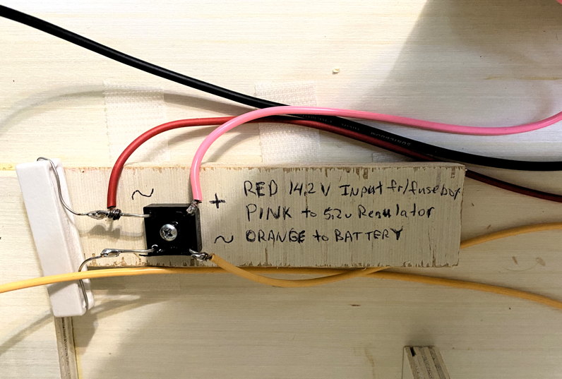
Important: 14.2 V is required as the feed into the diode switch so the float voltage onto the SLA battery is idealized.
We had been using an HP server supply modified to serve 14.2 VDC, and that was ideal.
But a 13.8 V or lower supply, to feed the radios, is now cheaper and much more common, so instead of using a 14.2 V supply to the entire system, we add a cheap, readily available off-the-shelf Meanwell brand, 14.2 V supply to feed just the Raspberry PI/digital section (including backup battery) of the node.
The schematic needed 3 diodes.
The nice thing about the bridge rectifier is that it gave us the diodes we needed in a single package and it had a screw mounting hole.
If you get a bridge rectifier with 1 amp diodes or larger, this is fine.
|
|
|
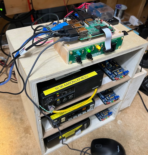
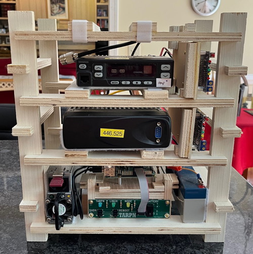
Above:
example fully assembled node boxes.
Top is a KM4EP cabinet.
Bottom is an NC4FG cabinet.
|
|
Parts for the switchover/trickle charge circuit
Parts list:
- Sealed Lead Acid battery (SLA)
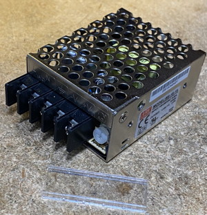
- Meanwell RS-15-15 Specifications [meanwell.com]
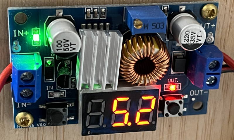
- DC-DC regulator device with 5.2 V adjustable output
- 6 or 7 inch short USB cable - Amazon has some 7 inch and .5 foot cables - any length cut down to 6" or so if home-brewing the regulator-output connection
- some scheme to mount the regulator (I use nylon #8 hex nuts McMaster-Carr 90089A305 (100) for $2.62)
- double face tape for permanently attaching the Meanwell to the top of a shelf within or on the top of your node cabinet.
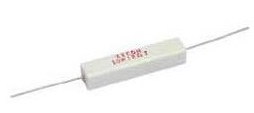
- 50 Ohm (+/- 10% on value) 5 or 10 Watt resistor -- the photos below show a 56 Ohm 5watt resistor.
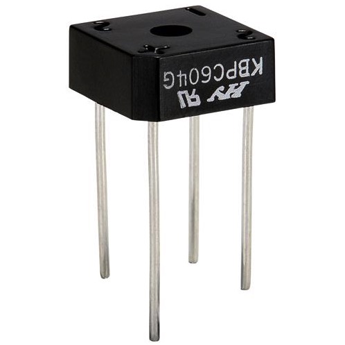
- Bridge Rectifier
- (2) female Crimp-on lugs for the battery
- 3-foot of hookup wire, 16 to 20 AWG.
You'll want 4 different colors, not including white and green.
This wire passes at most 1 Amp at 14.2 VDC
Jameco 18 gauge hookup wire
- TARPN Control Panel or other switch
The Bridge rectifiers come from Parts-Express -- Part # 050-030.
They are 400V 6A Bridge Rectifiers
A bridge rectifier is four diodes embedded in one package in exactly circuit needed to turn the output of a transformer, which will be alternating current, into direct current.
There are many AC to DC power supplies (like the Astrons used by many hams for their mobile radios when used in the house).
Consequently, bridge rectifiers are pretty inexpensive.
We aren't going to be using it for that.
We'll be using just 3 of the diodes in the package as part of our switchover and charger circuit/
It just works out that the arrangement of the diodes in a bridge rectifier are perfect for what we needed, and the bridge rectifier is as cheap as, and easier to mount, than 3 individual diodes.
|
|
The resistors (I usually buy them in quantity and keep some in stock) come from
Parts-Express and are 47 Ohm 10W Resistor Wire Wound 5% Tolerance -- Part # 016-47
The gel cells I've used so far run from 2 to 4.5 amp-hour.
Here is my favorite model because it fits in the housings we've been using:
Parts Express has Power-Sonic PS-1220 Sealed Lead Acid Battery 12V 2.5Ah -- Part # 140-360
Amazon has also had these in quantity 10 for lower cost per unit.

The variable output 14.2 V power supply is a Meanwell RS-15-15
See also:
Purchasing and wiring a Meanwell RS-15-15
Adjustable output regulator to power the Raspberry PI.
See also
5.2 V Regulator
Schematic of the robust power supply
Note that the AC to DC supply should have 14.2v output in order to float the GelCel propertly.
Note: The
- side of the Meanwell, the
- side of the battery, and the
-in for the LM2596 variable regulator can all be tied to the same ground bus used for the radio power supply and the radios.
Photo showing method of constructing the robust power supply.
Here's the bridge rectifier and trickle-charge resistor.
Step by Step Instructions.
- Before proceeding:
- Obtain a switched AC power outlet strip, preferably fused and with a Ground-Fault circuit breaker for ultimate safety.
Plug this into AC power.
- Unplug the Raspberry PI power from the Raspberry PI.
- Remove the memory SDcard from the Raspberry PI.
- turn off the battery switch and
- disconnect the positive lead from the battery.
- See detail on Meanwell AC wiring: Wiring Meanwell RS-15-15.
Note that the Meanwell section includes details for securing the supply and inspection of AC safety and DC output.
At this point the Meanwell supply is not protected from curious fingers, so be careful in all steps where the Meanwell power cord is plugged in!
- Turn off the AC power strip powering the Meanwell AND unplug the power cord.
- Secure the bridge rectifier circuit and the DROK regulator device.
- Verify DROK is getting power:
- With the AC power strip turned off, plug the Meanwell's power cord into the strip.
- While securing the screw-terminal end of the Meanwell so no stray conductors or body parts can reach it, turn on the power strip to power-on the Meanwell.
- Observe that the DROK supply has lit its LEDs.
- Turn off the AC power strip, removing power from the Meanwell.
- Restore power to the Meanwell supply by turning on the AC power strip.
- Adjust the output voltage of the DROK power supply.
- Turn off the AC power strip.
- Turn off the battery connect switch.
- Test the battery with the positive lead disconnected and make sure the is at around 12 Volts.
- Test the voltages at the battery switch (without the battery in circuit) and adjust the Meanwell so the battery leads are at 13.8 V.
- Adjust Meanwell supply's output voltage to as close to 13.8 V as you can manage.
- Turn off the AC power strip.
- Finish assembly of your node box sufficient that the Meanwell is secure and protected against stray body parts.
The Meanwell's cord should be secure such that tugging on the cord will not affect the safety of the connections.
See Wiring Meanwell RS-15-15.
- Attach the battery to its leads.
- Turn on the battery connect switch.
- Turn off the AC power strip (removing mains power to the Meanwell) and verify that the DROK stays lit.
- Turn on the AC power strip.
- Plug the USB from the DROK into the Raspberry PI.
- Observe the power light on the Raspberry PI.