See also
PWRMAN,
TNC-PI,
Wiring for Icom HT
Basebox slideout board complete with the Oscilloscope mounting board pre-drilled with the four holes to mount the scope and the 3/8 inch hole for power and audio wiring
HP 1200 watt Power Supply (modified to provide 13.8v) with +/- power output tabs
17" of Velcro or Scotch fastener Tape ( 2 1" strips to fasten the Chuangruifa 13.8v/9v converter, and 2 7.5" strips to fasten the HP Power supply}
6 yellow flat quick disconnect terminal connectors
1 yellow flat ring terminal connector (to the fuse box)
2 15 Amp PowerPole pins
6 30 Amp PowerPole pins
3 Fused Red/Black PowerPole connectors
1 Light blue PowerPole connector
1 Black PowerPole connector
1 Fuse box
2 3 Amp fuses
2 10 Amp fuses
1 Ground bar
4 #10 x 1 inch metal screws (2 for fuse box and 2 for ground rod with washer below the ground bar)
2 1/4 inch flat metal washers (below the ground rod)
1 Completed Oscilloscope board
4 Hex threaded standoffs (for the Oscilloscope board mounting to the Oscilloscope wooden board)
4 Screws (through the Oscilloscope wooden board into the Hex threaded standoffs above)
4 Nuts (that hold the Oscilloscope board to the standoffs)
63 inches of 14 gauge red/black zip cord (cut to the following lengths, 6", 10", 20" and 27")
12 inches low gauge zip cord ( for audio output from Oscilloscope board)
1 Chuangruifa 13.8v to 9v DC/DC converter
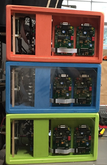
Portable, small node packages for demo
This is a project to make conveniently small node packages for demonstration and test.
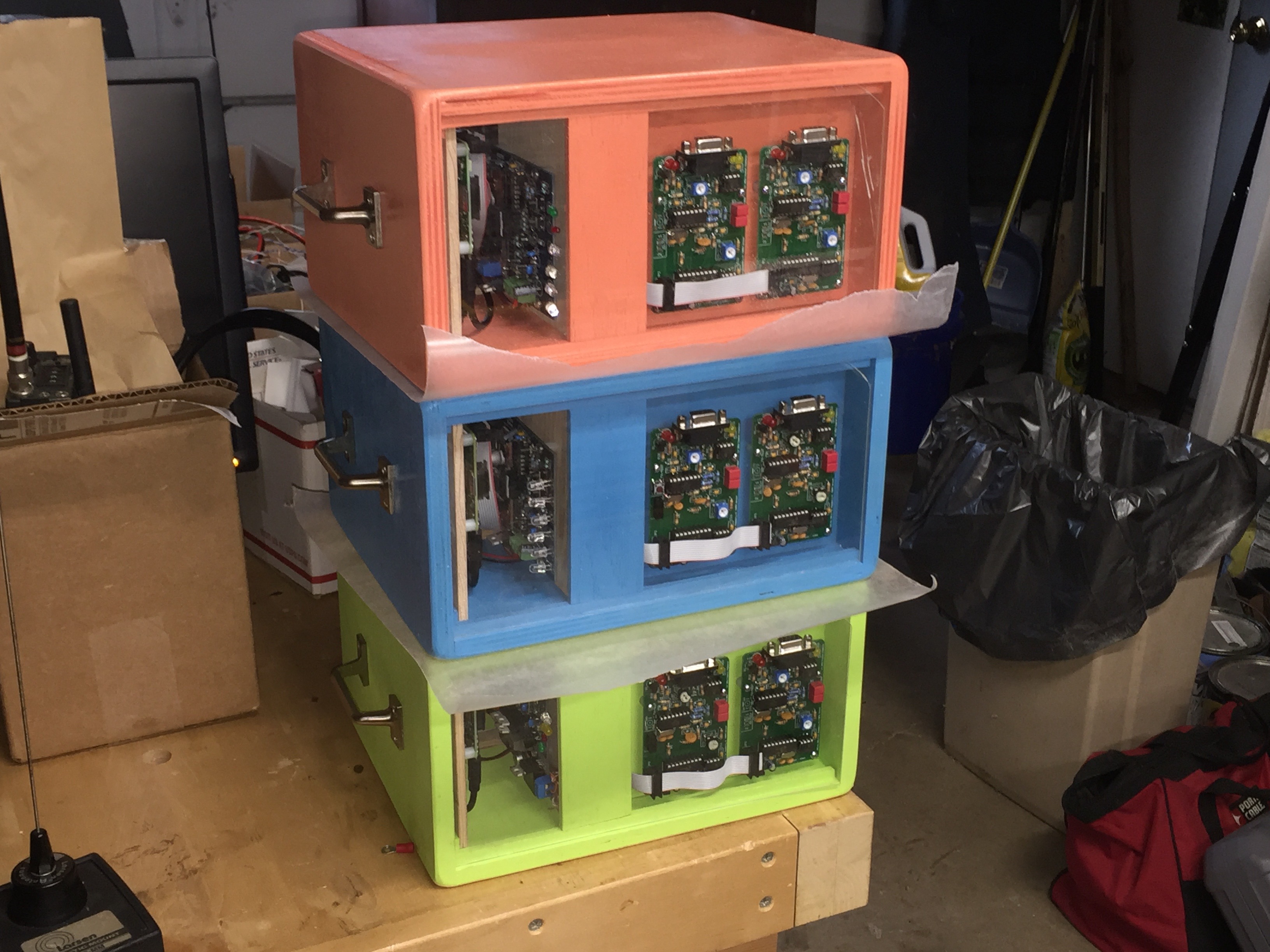
The result was 3 two-port TARPN nodes with low power synthesized ham radios on each port.
The nodes are about a foot wide, 7" high, and 10" deep, with convenient handles.
The equipment is secure for transport and, except for the antennas, is ready to use immediately when AC power is applied.
The equipment was designed as a group effort.
Fin-NC4FG did all of the cabinet design, woodwork, painting, wiring, and mounting of the components.
Tadd-KA2DEW provided the radios and constructed the TNC to radio cabling.
Tadd, Billy-KE4VNC, and Jenna built the 6 TNC-PI kits.
Steve-W4RFQ supplied the PWRMAN1 and 2 units.
The nodes are based on TNC-PI v2.3b, Raspberry PI 2b and 3b boards, PWRMAN1 and PWRMAN2 modified to use 9V battery as a backup source, and Icom IC2AT (2 meters), IC3AT (220) and IC4AT (440) handie-talkies.
The nodes will be low power, 150mW on two bands, each.
The handie-talkies are from the early 1980s and were cheap and easy to configure.
They also draw very little power, 300mA during low power transmit.
17mA when squelched.
The HTs are powered from a switching regulator and are given 8.4volts regulated.
|
|
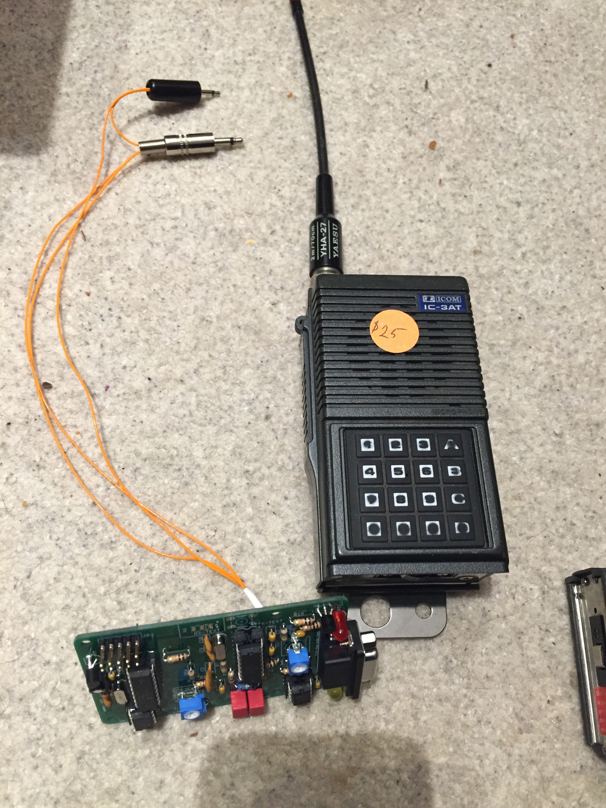
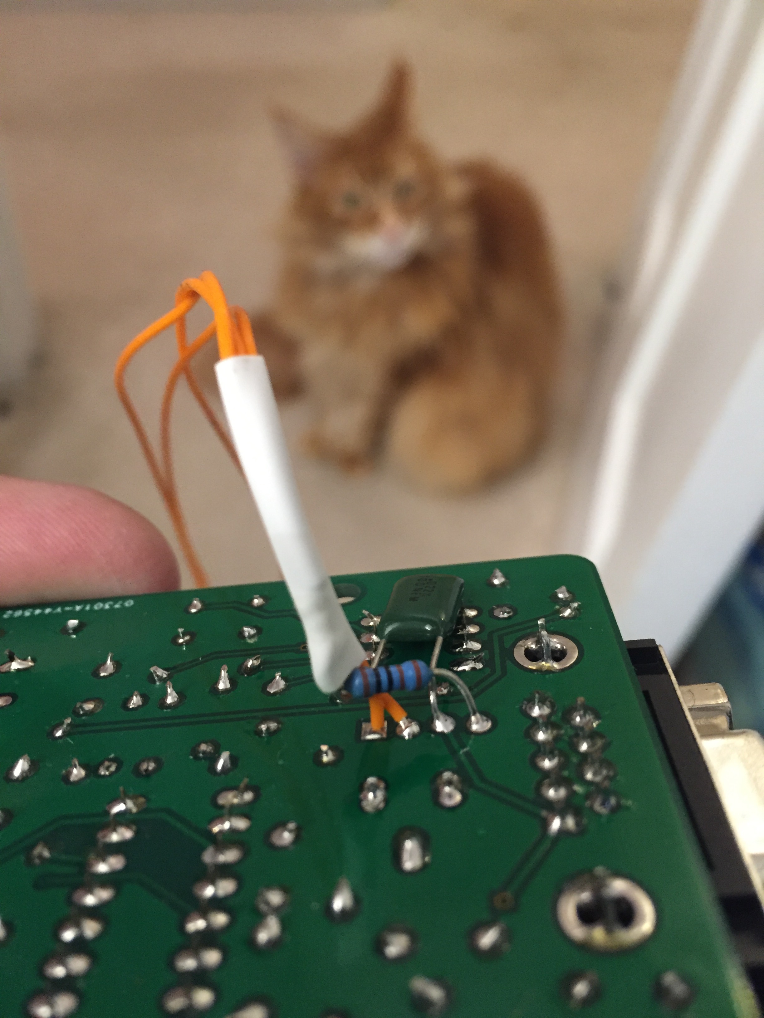
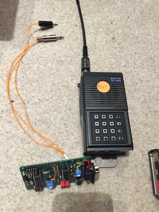
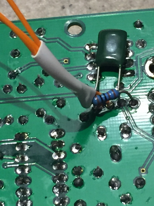
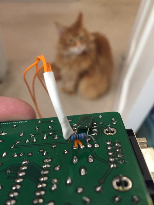
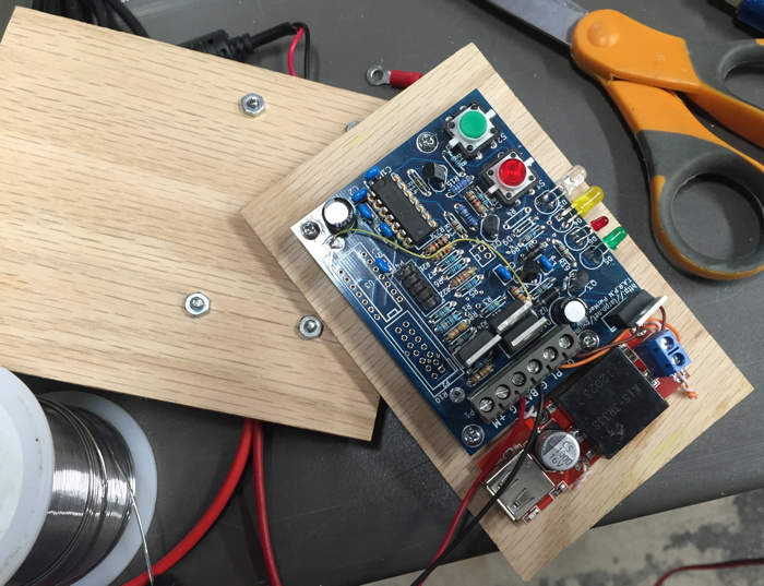
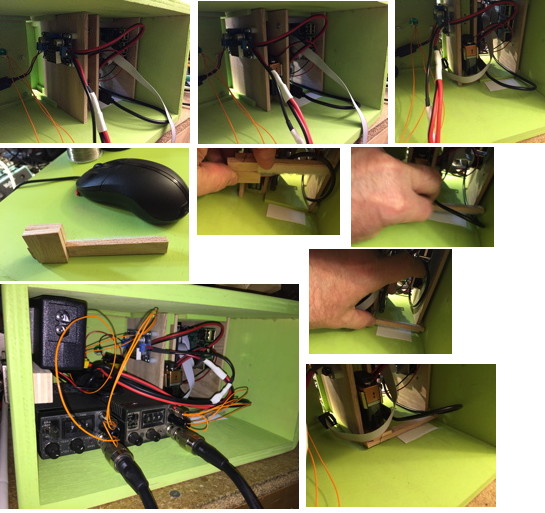
The next several photos show the connection from the Icom HT to the TNC-PI for PTT and audio.
We did something different by connecting the audio and PTT lines directly to the back of the TNCs.
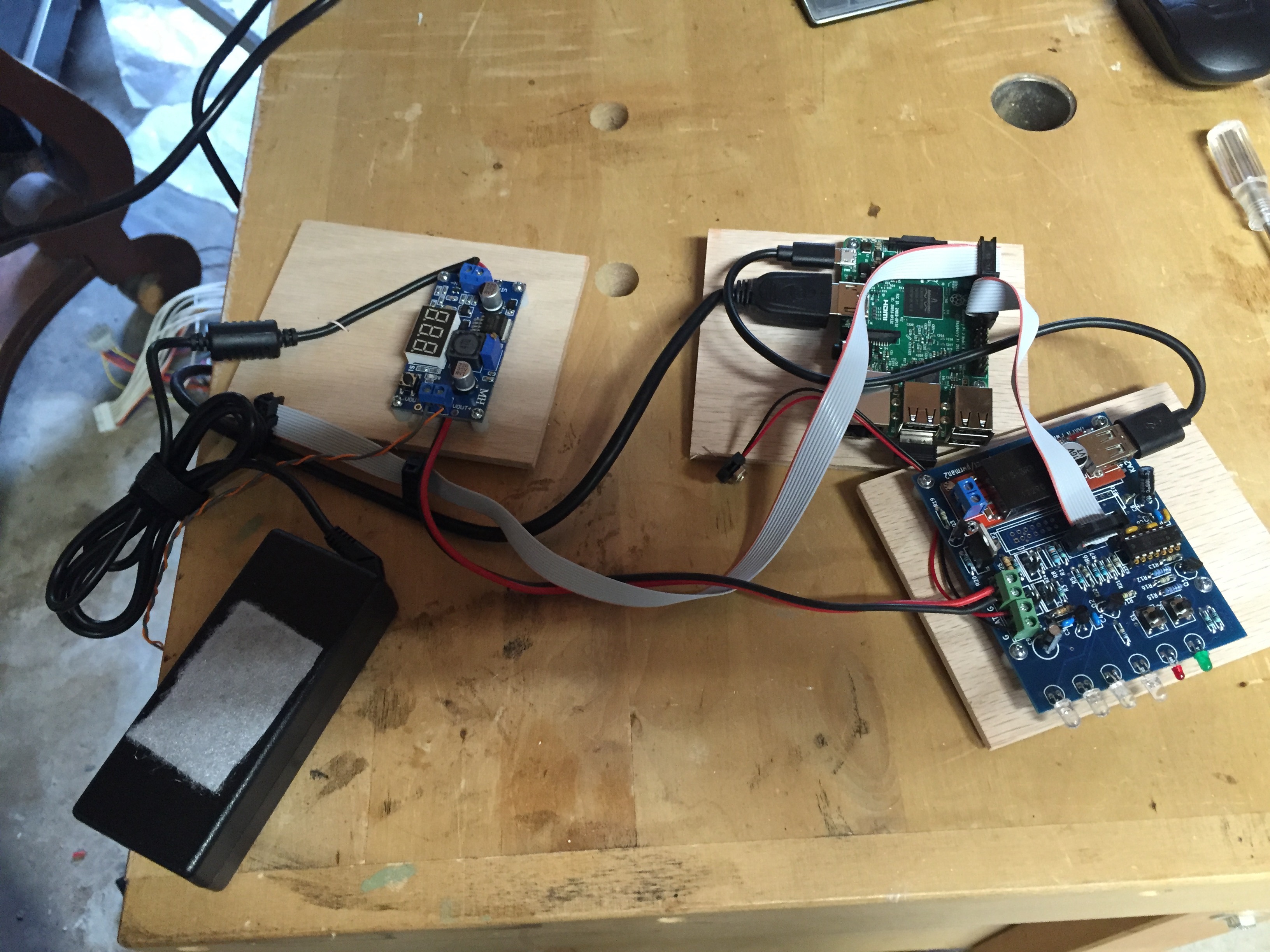
The Raspberry PI, PWRMAN2 and the voltage regulator for the HTs are each mounted to separate vertical slide-in carrier cards.

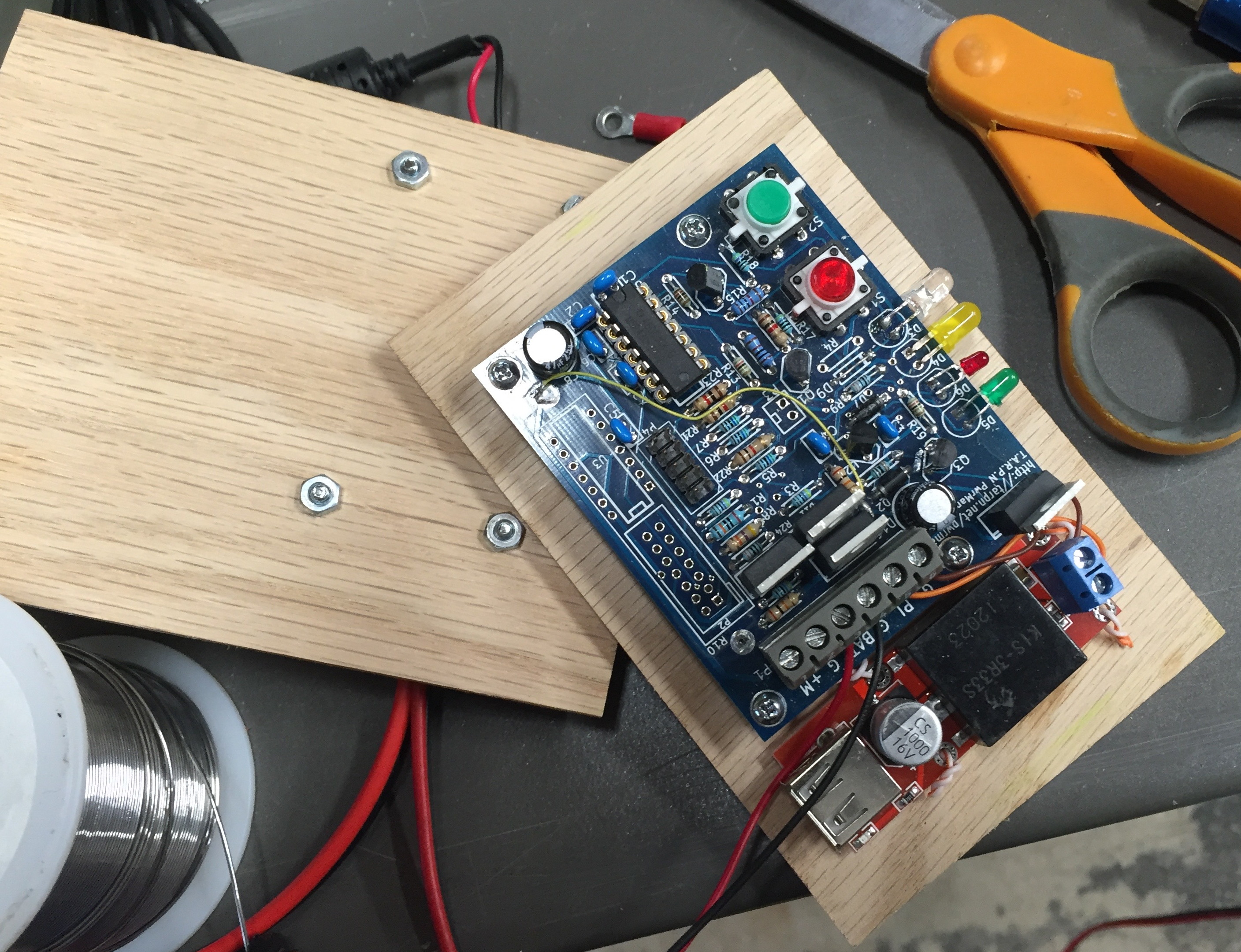
One of the boxes is equipped with a PWRMAN1 board since we didn't have enough of the new PWRMAN2 boards at time of construction.
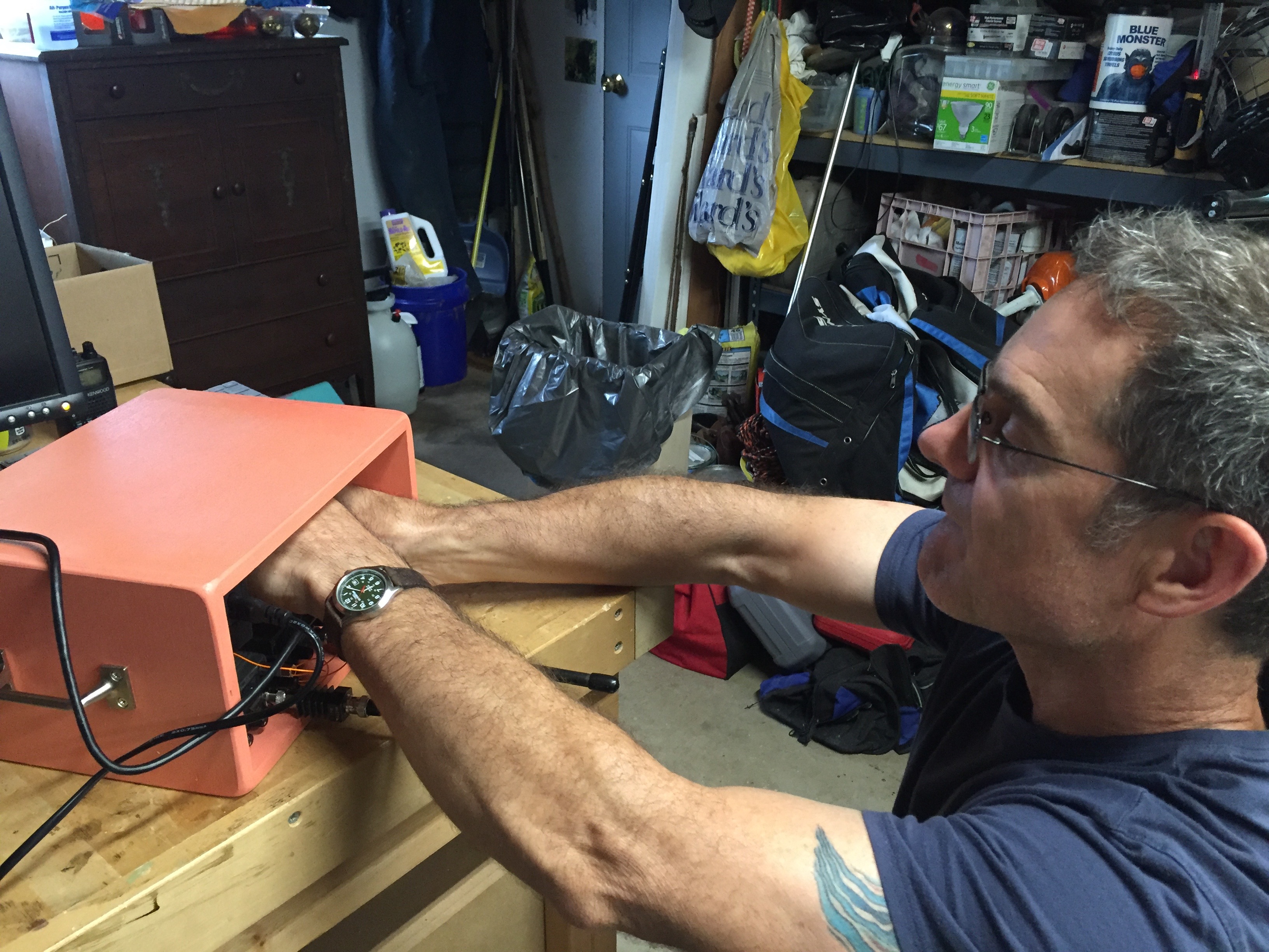
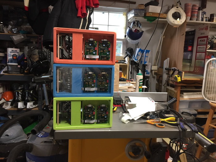
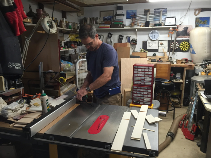
Here is Fin, NC4FG, working on the innards of the RED node.

On the upper left you can see the 2amp 12v power supply which will run the node.
The HTs have separate volume and squelch controls, separate mike and speaker plugs, thumbwheel controlled frequency, and a BNC connector.
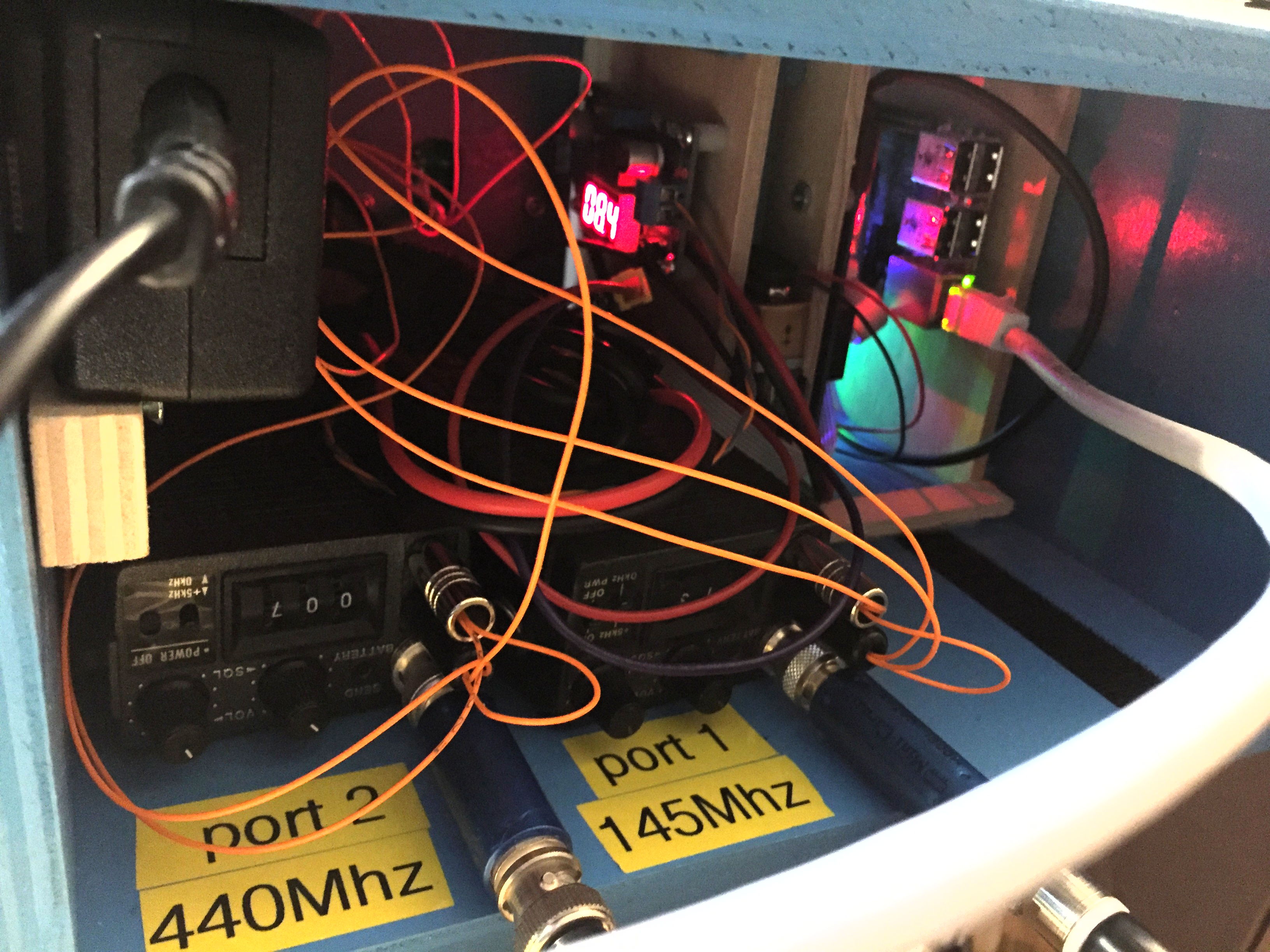
We placed 10dB attenuators in between the BNC connector and the ducky because we don't need much RF power to go across a room and this keeps the stray RF inside the box to a minimum.
On right side of the box you can see the vertical slide-in carrier cards -- look for the blond colored wood pieces.
From left to right they are: regulator, PWRMAN, Raspberry PI.
Power to the HTs is attached to the bottom of the radio where the battery is supposed to slide.
The disconnects on the power leads are PowerPole using black/yellow connectors, to differentiate them from the 12v black/red connectors used in other projects.
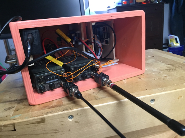
Because we wired to the back of the TNC-PI, not much room is needed above the TNC, and the box looks very clean.
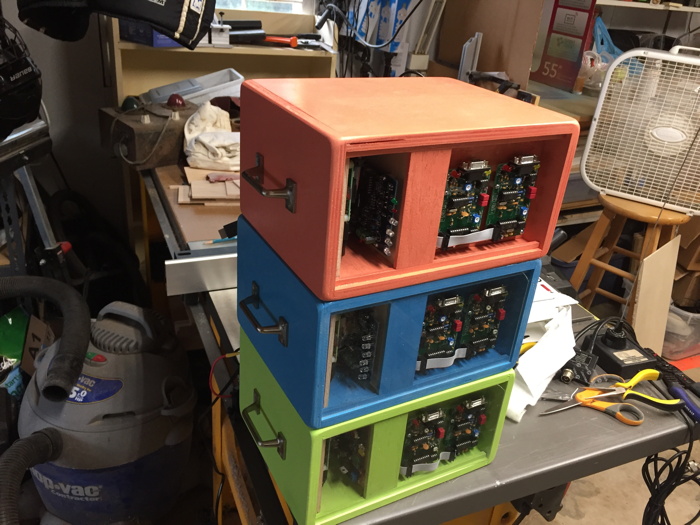
Fin is using the table-saw to make a device which will hold the stack of boxes together during transport.

Installing the carrier cards into one of the cabinets
Click to go to a new page with enlargements and comprehensive descriptions.
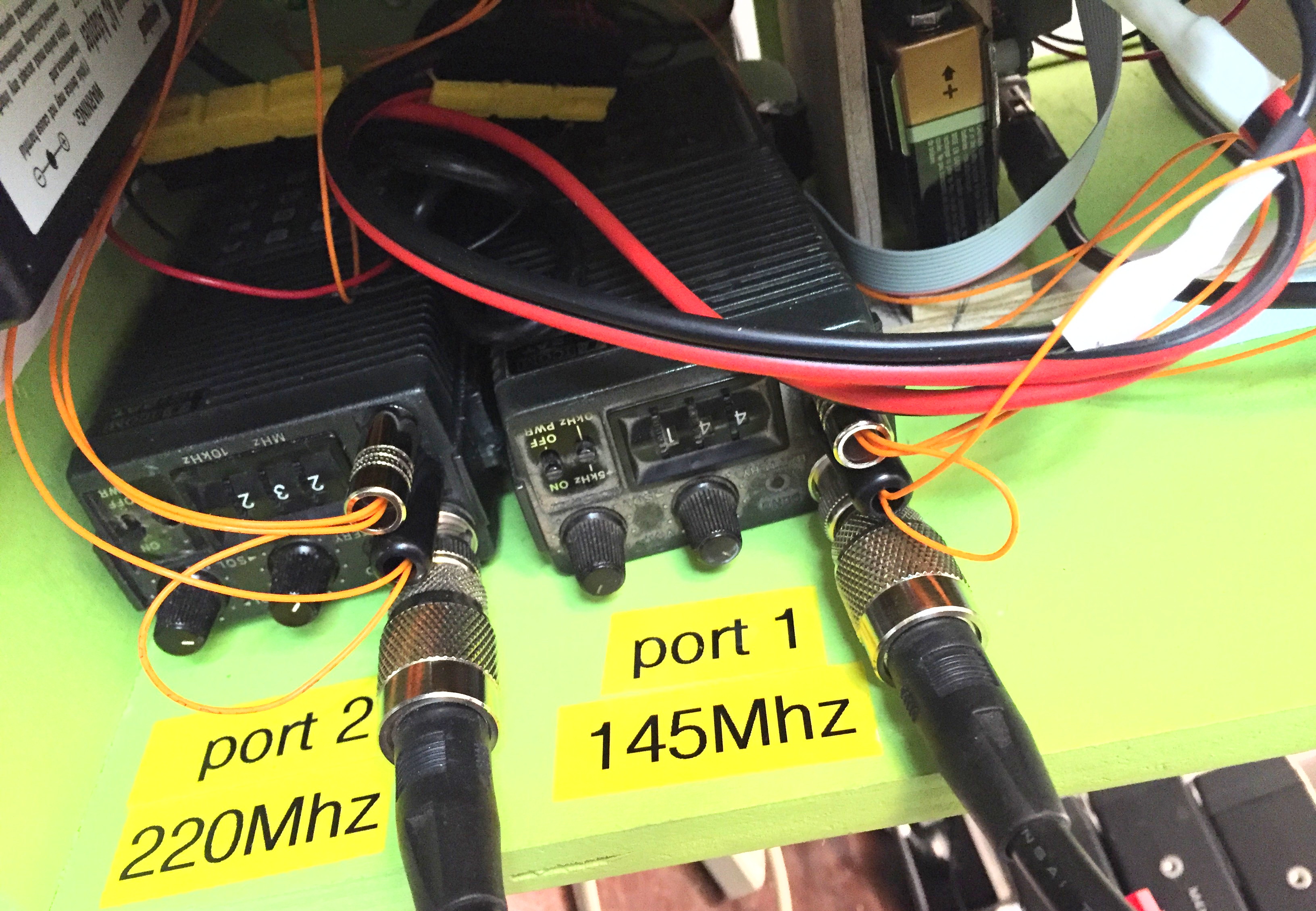
I put labels next to each radio so you could tell what port designation each had.
On the front of the box the left TNC-PI is port 1 and goes with the left radio (from the perspective of the front of the cabinet).

Here you can see the regulator for the HTs reporting 8.4 volts.

More and better photos will follow!