| home | builders | Search |
| builders ➜ Radios & Wiring for Radios ➜ NinoTNC to Kenwood TK 790 commercial 2-way mobile |
| home | builders | Search |
| builders ➜ Radios & Wiring for Radios ➜ NinoTNC to Kenwood TK 790 commercial 2-way mobile |
Thanks for info and photos by John N3XKD from the Kentuckiana TARPN, and for page updates and more photos by Don N2IRZ from the Atlanta TARPN
The TK790 is a 45 (or 110 watt) 2m transceiver made for commercial 2-way use. They are available surplus/used for under $100.
At this time we've established that they are useful for 9600 packet radio using the NinoTNC, but have not yet tested them at a great distance. That testing is being performed, and the results will update this page.
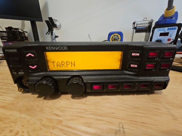
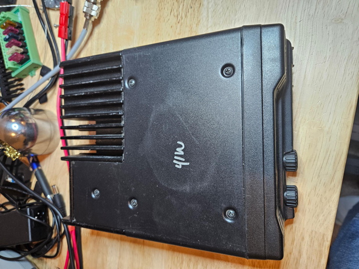
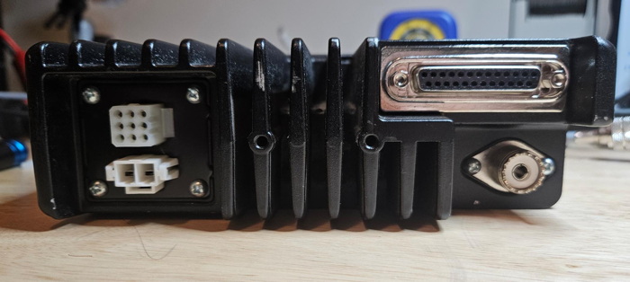
VARIANTS:The TK-790 comes in a few different variants, all of which can be programmed for the 2 meter band:
Kenwood also offered the TK-690 (6 meter) and TK890 (70 cm) models, which are likely to be similar enough for these instructions to work, but we have NOT tested any of this on those models. If you have either model, please let us know if there's anything we should add to this page, thanks.
1. Internal Resistor Jumpers - For Power On
No parts are needed, but you will need a Philips screwdriver, a temperature-controlled soldering iron with a needle tip, small-diameter rosin-core solder, needle tweezers suitable for picking up tiny surface-mount resistors, a very steady hand and good eyes or a decent magnifier. A cell phone can be used as a magnifier.
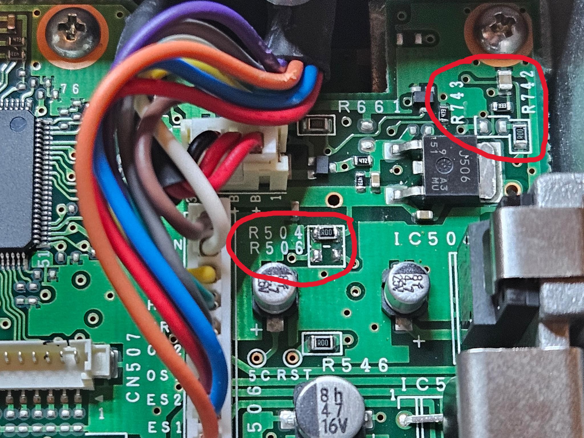
Many of these radios will seem to not power on, as they are usually set up for Ignition Sense for a mobile installation. If you adjust the Jumpers inside the top case as shown below, it will remove the requirement for Ignition Sense, allowing the unit to power on using the power button.
Remove the top cover by unscrewing the five screws.
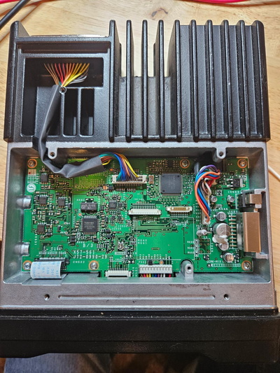
Identify the two areas of interest on the board.
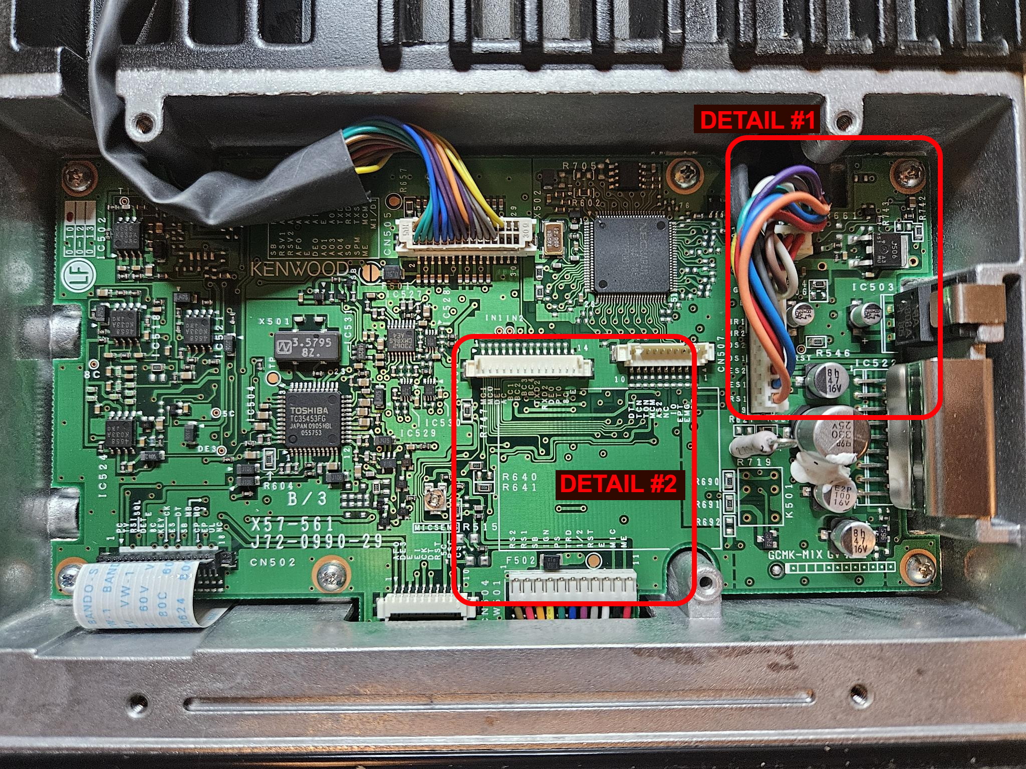
Unsolder and move the jumpers IF NEEDED. These are zero-ohm resistors, so anything that shorts out the right places is fine (e.g., wire)
2. Internal Resistor Jumpers - Data Input Mode
This jumper sets whether the DB-25 input is microphone audio or data audio. You want data audio.
No parts required, but the same tools as above
You can expect to have to move R640 to position R641.
DETAIL #2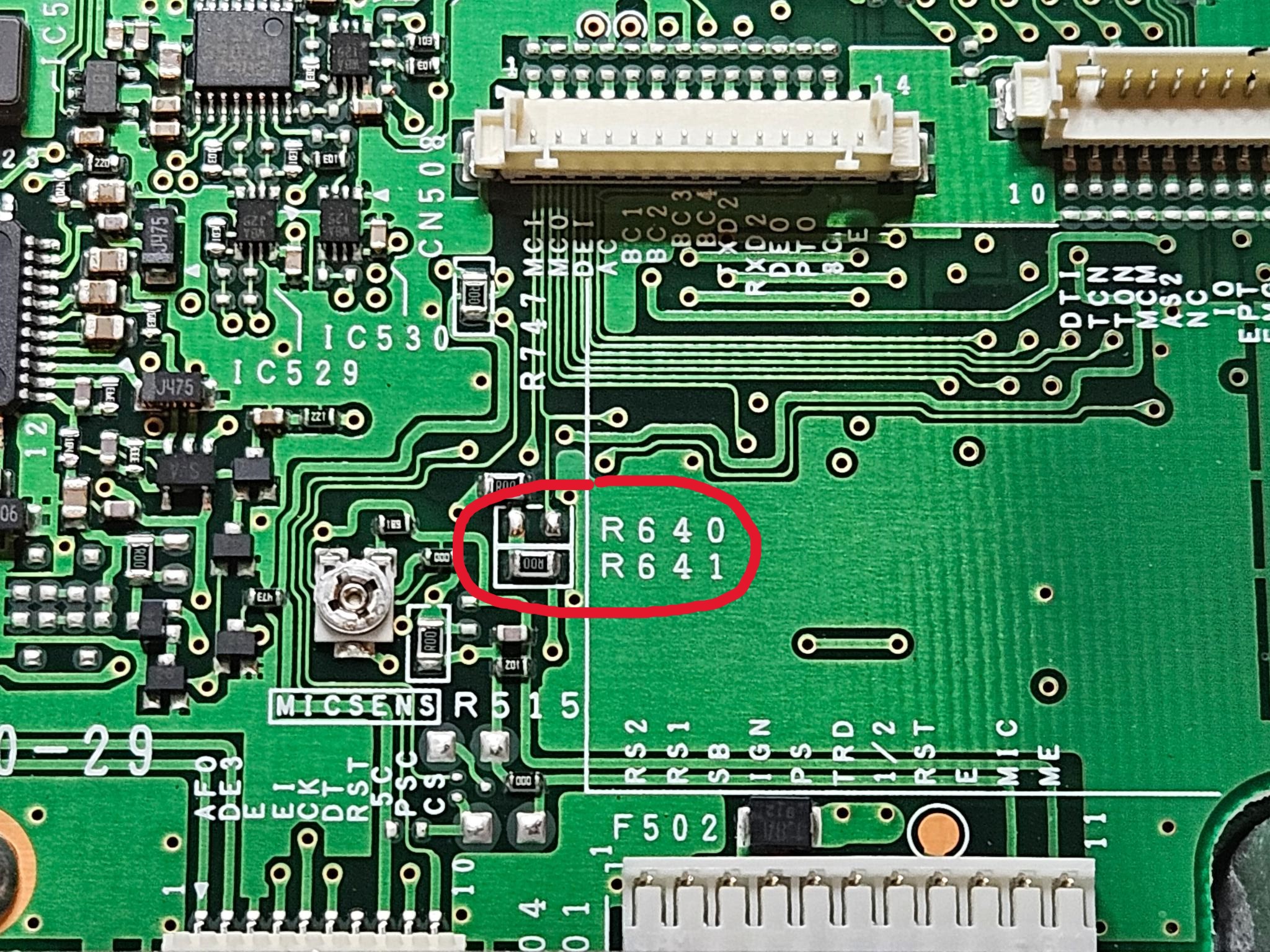
This completes the internal jumper configuration
3. Connections Needed for 9600 Baud
This section explains where the four connections for packet operation are found.
Parts Required:
You will also need a temperature-controlled soldering iron with a needle tip, some hot-melt glue, a steady hand and good eyes (or a magnifier).
Start by identifying the area of interest: A small through-hole on the circuit board (called a Via), which is the pick-off point for RXA.
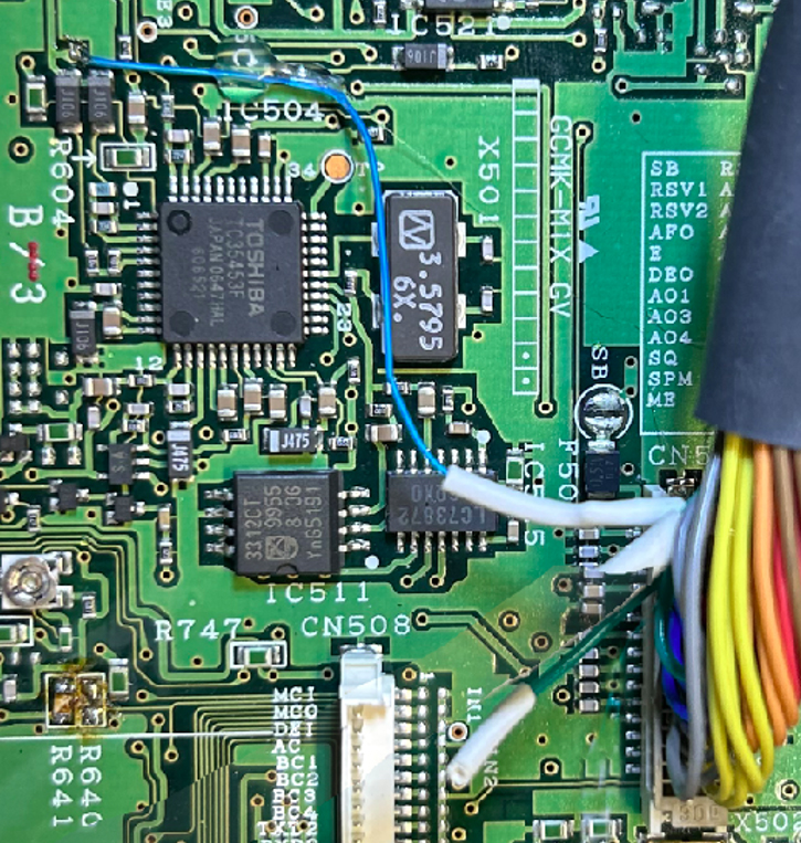
This image shows the front left of the top circuit board. Note the white ribbon cable. The insets show the board layout and a close-up of the via with the wire placed inside it, ready for solder.
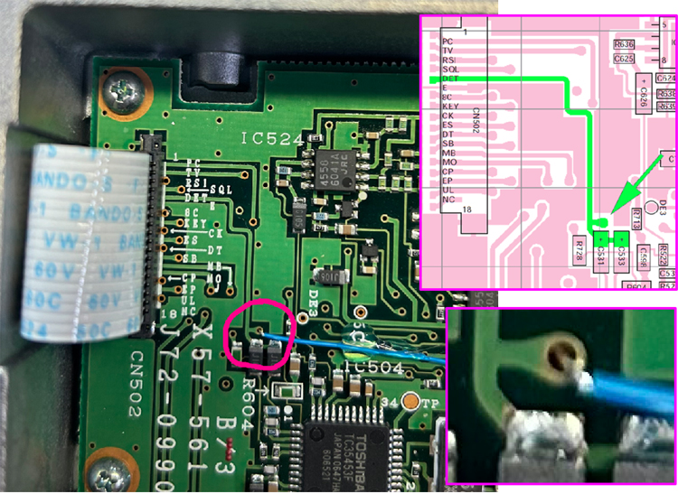
This image shows the green RSV2 wire cut, stripped, tinned and the #30 RXA wire with the heat-shrink tubing on it, ready for soldering.
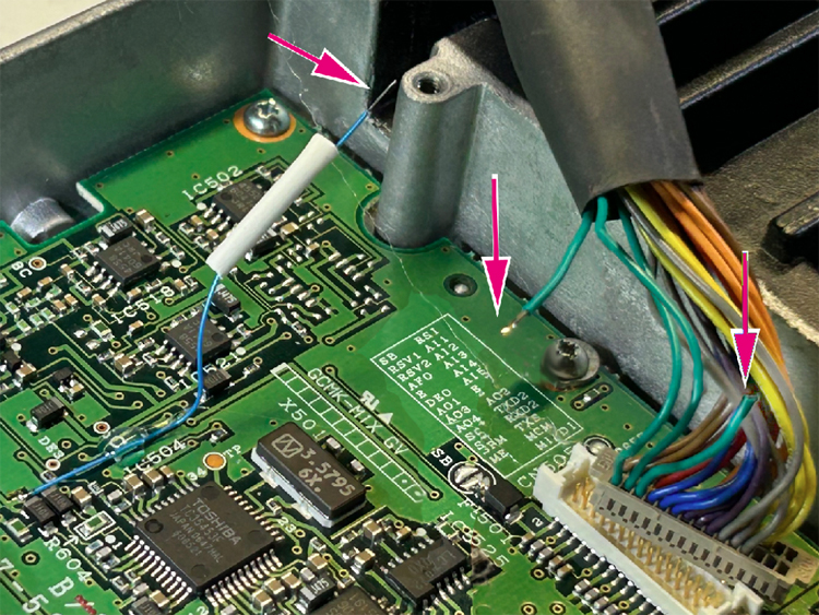
This image shows the completed work
4. Wiring for the TNC-Radio cable
This cable connects the NinoTNC to the Radio.
Parts Needed:
Connect the wires as follows:
DB-25M ----- DE-9M
Pin 13 ----- Pin 1 (TXA)
Pin 7 ------ Pin 6 (GND)
Pin 15 ----- Pin 3 (PTT)
Pin 16 ----- Pin 5 (RXA)
This image shows the DB-25 M connector with all seven pins soldered, including the (optional) N2IRZ RSSI Board signals.
From left to right: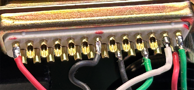
5. Programming Details
The radio must be programmed to feed PTT to the DB-25 connector.
Using the KPG-44D software and the KPG-43 programming cable (both available from bluemax49ers.com), connect to the radio and select "Edit/Function Port". Set Radio 1 AI1 to EXT PTT as shown.
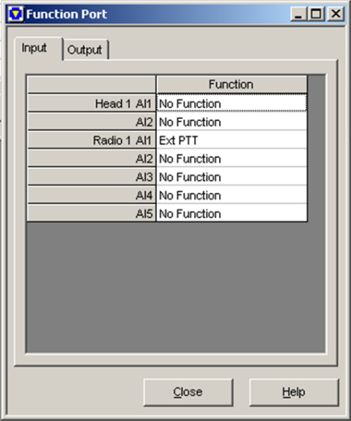
Now select Edit/Optional Features and check the box for "Ext PTT w/MIC Mute. Uncheck any other boxes.
(Note: You might want to set Minimum Volume to 0 and Timed Power Off to Off.)
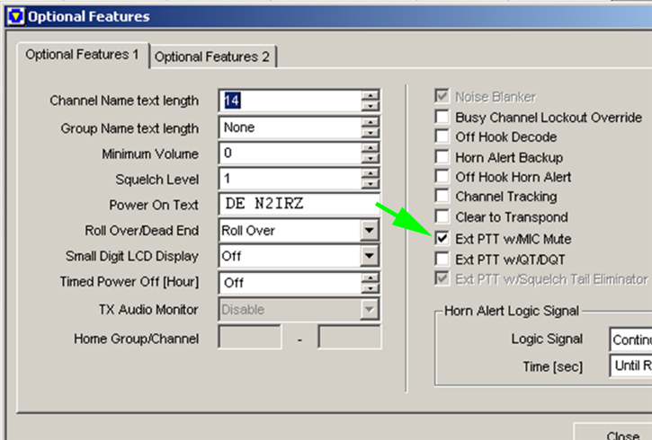
After setting everything else as desired, load the program into the radio.
6. Converting the power connector to Anderson PowerPoles
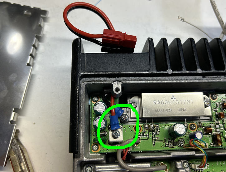
This one is fairly simple. The original power cable ends in a Molex-type connector, which may be inconvenient and thus, if inconvenient, this can be converted to Anderson Powerpoles. The key is that the wires for the power connector have ring terminals held in place by screws inside the radio, as shown here.
Parts Needed:
At this time, you might want to reinstall the top cover and anything else we've forgetten to mention.
7. RSSI Signal Connections
The TK-790 does not have an RSSI indicator, which would be useful when setting up a link. This section explains the connection details to obtain RSSI, Ground and +13V power from the radio, with which the N2IRZ RSSI Board can give a visual indication of signal strength. All of these signals are available on the DB-25 connector.
Parts Needed:
NOTE: These instructions do not explain the setup and programming needed for the RSSI board. We are only picking off the needed signals!

Note that F501 (500 mA) is there in case of an external short on the +13V pin. Exact replacements may be difficult to find, so take extra care to avoid a short circuit.
For more information, consult TNC and Radio Adjust and Test or the operations guide for your TNC.