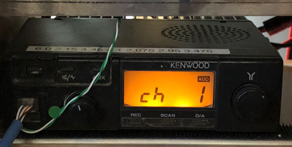
Kenwood TK 705d/805d Modifications
by Jim WB2LHP My email is good in
QRZ
This modification does not impact the radio's operation as a 2-way FM voice radio.
It also leaves it compatible with the generic TARPN TK radio to TNC cable, though you'll want to make a custom cable to take full advantage.
My mod disables the off-hook signal to the front panel mic jack on pin 6 and replaces it with the fixed audio from the high side of the volume control, post discriminator filter.
Here is the procedure.
It works for either the 705D or the 805D.
This is really small work.
I use a bright light, magnifying glass, small tip iron and lots of coffee to do the work.
I also use 30 gauge Kynar wire-wrapping wire for the jumper.
Do
not attempt with stranded wire.
This is SMALL work so take your time.
Total time for me was just under an hour.
Get the Service manual here.
- Get four bowls as a place to hold the four different sets of screws.
There will be quantities 4, 4, 2 and 1 screw.
You might write a note on four pieces of paper which will be placed in the bowls to identify the sets
- (4) Top/Bottom Cover,
- (4) RF-deck metal cover,
- (1) LCD retaining screw,
- (2) Control Board.
- Remove the 4 screws holding the top and bottom covers of the radio
- Remove the covers and set aside
- Carefully unplug the speaker and set it aside
- Lift off the speaker holder and set it aside
- Remove the volume and tuning knobs
- There are 4 plastic tabs holding the front panel to the radio. Gently and carefully lift the tabs just enough to slide them off the retainers. Remove the front panel and set it aside
- There are some foam pads surrounding the buttons and controls. If they are disintegrating, take a small brush and remove them. Otherwise you can leave them in place
- Remove the retaining screw for the LCD display. Unplug the display and set it aside.
- Remove the 4 screws holding the metal cover to the RF deck. Remove the cover and set it aside
- The button are free and loose. Remove them and setting them aside
- Remove the 2 screws holding the control board to the radio body
- Carefully unplug and remove the control board
- You are now ready to perform the fixed receive audio mod.
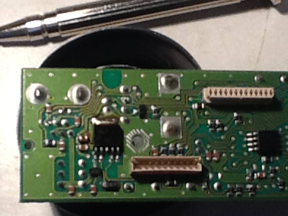
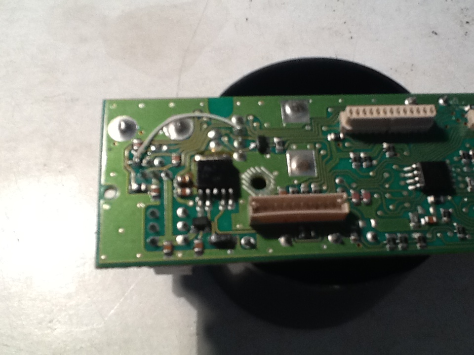
- On the back side of the board, locate and remove R254 (marked 102).
It's near the mic jack connections, sort of in between the mic jack mounting tabs.
This removes the off-hook signal from the mic jack pin 6 and simulates the off-hook condition, which we want.
- Install a small jumper from mic jack pin 6 to the high side of the volume control. See the pictures for clarity.
This brings the fixed level post discriminator filter to the mic jack. I use 30 gauge Kynar wire-wrapping wire for the jumper.
- Plug the control board back in place
- Put back the 2 screws holding the control board to the radio body
- Restore the buttons to the control board
- Put the metal cover over the radio body. Attach 4 screws to hold the metal cover.
- Plug in the LCD display and restore the retaining screw
- Restore the front panel
- Attach the volume and tuning knobs
- Put the speaker holder into place
- Plug the speaker in and restore it to its position on the speaker holder
- Reattach top and bottom covers
- screw the top and bottom covers down with the 4 remaining screws
That's it. Mod done.
Now you have fixed receive audio going to your TNC independent of the volume control setting and you can monitor the receiver through the speaker.
Now you have fixed receive audio going to your TNC independent of the volume control setting and you can monitor the receiver through the speaker.
You asked me if this mod would provide any significant improvement over what you are doing now. The answer is yes and here's why.
The high side of the volume control is a fixed level at the right level and impedance for the TNC-Pi and probably most others. It is linear and low distortion. Most 2-way radio speaker amplifiers are very noisy and high in distortion, about 10%. They're made for volume, not quality. Using this pickoff point for the receive audio will produce better decoding results and removes a couple more variables from the equation. This is how the Maxon radios work. As far as using the mic jack for the transmit audio, these issues are not as prevalent. As long as you keep the input level low and quiet, this will work well for 1200 work. Getting to the modulator directly in this radio is not easy. Inserting a 680K resistor in series with the mic input to the radio will create a 100:1 voltage divider at the mic input and give you a better handle on the drive level setting. I'll have to try that but first I need to get my hands on some RJ-12 connectors and cables. I don't have any tools for that work so I'll grab something off of eBay.
So that's the mod. One cable from the Kenwood mic jack to the TNC-Pi DB-9. I like that. Clean and easy.
Making the new TK radio cable
During assembly, I suggest crimping the wires to the RJ12 first, then solder the DE9.
Parts and tools required:
- DE9 solder-pin male connector
- DE9 shell
- RJ12 crimp-on 6-bin connector
- 10" piece of CAT5 or CAT6 wire
- two 4.7k resistors
- soldering iron, solder
- RJ12 crimping tool
I have had very good luck with DE9 connectors from
Parts Express.
I recommend:
090-550 Parts Express 9 Pin Male Solder Type D-Sub at 45 cents each and
Try to find real copper CAT5 or CAT6 wire.
There are 3 critical signals, plus ground, connected to the TNC-PI.
Those signals connect to the TNC on these pins of the DE-9 connector:
I have arbitrarily selected color coding for the signals using colors available on typical CAT5 wire.
I chose CAT5 wire because it is easy to crimp into an inexpensive RJ12 connector.
The color codes are shown for the wires which are connected directly from the DE9 to the CAT5.
Pin 1, TxData, is fed through a resistor divider and then into the Blue wire.
Click on the images to enlarge
The resistor divider allows for a much less stiff adjustment on the TNC-PI.
If pin 1 was connected to the mike/txaudio wire directly, the TXLEVEL pot R7 is so sensitive that it is almost
impossible to find the proper level to saturate the radio passband, without overdriving.
With the addition of the potentiometer in the DE9 connector, it is really easy to set R7.
Assembly
RJ12 Connector for Modified TK705d/TK805d
Please note that the RJ12 connector may be used even on Kenwood TK radios which have an 8-pin microphone connector.
The remaining unserviced 2 pins are not used in our application.
Also note that the standard Ethernet color codes were not followed and we're crimping the BROWN and BROWN/WHITE wires
into the connector but not connecting them at the DE-9 end of the wire.
Strip one end of the CAT5 wire such that there is about 3/4" of the colored wires free.
Cut the brown&white wire and the green&white wire.
Crimp six wires into the RJ12 connector as shown, cutting the green/white wire and the brown/white wire.
We’re connecting to 6 pins on the radio though only 5 are important.
Based on the image of the RJ12 just below, this is the order from left to right.
RXDATA - GREEN - volume-control-independent Rx audio
MIC — — BLUE
ME — — BLUE-WHITE — External Microphone Ground
PTT — — ORANGE
GND — — ORANGE/WHITE — PTT Ground
PSB — — BROWN - don’t care
Note! These wiring colors are not anybody's standard.
Please crimp with these colors.
The wire on the right end, brown, is not important except that they make it easy to place the other five wires in the connector.
NOTE: NEED IMAGE OF RJ12 assembled as described!
The colors are:
- green
- blue
- white/blue
- orange
- white/orange
- brown
DE9 Connector for Modified TK705d/TK805d
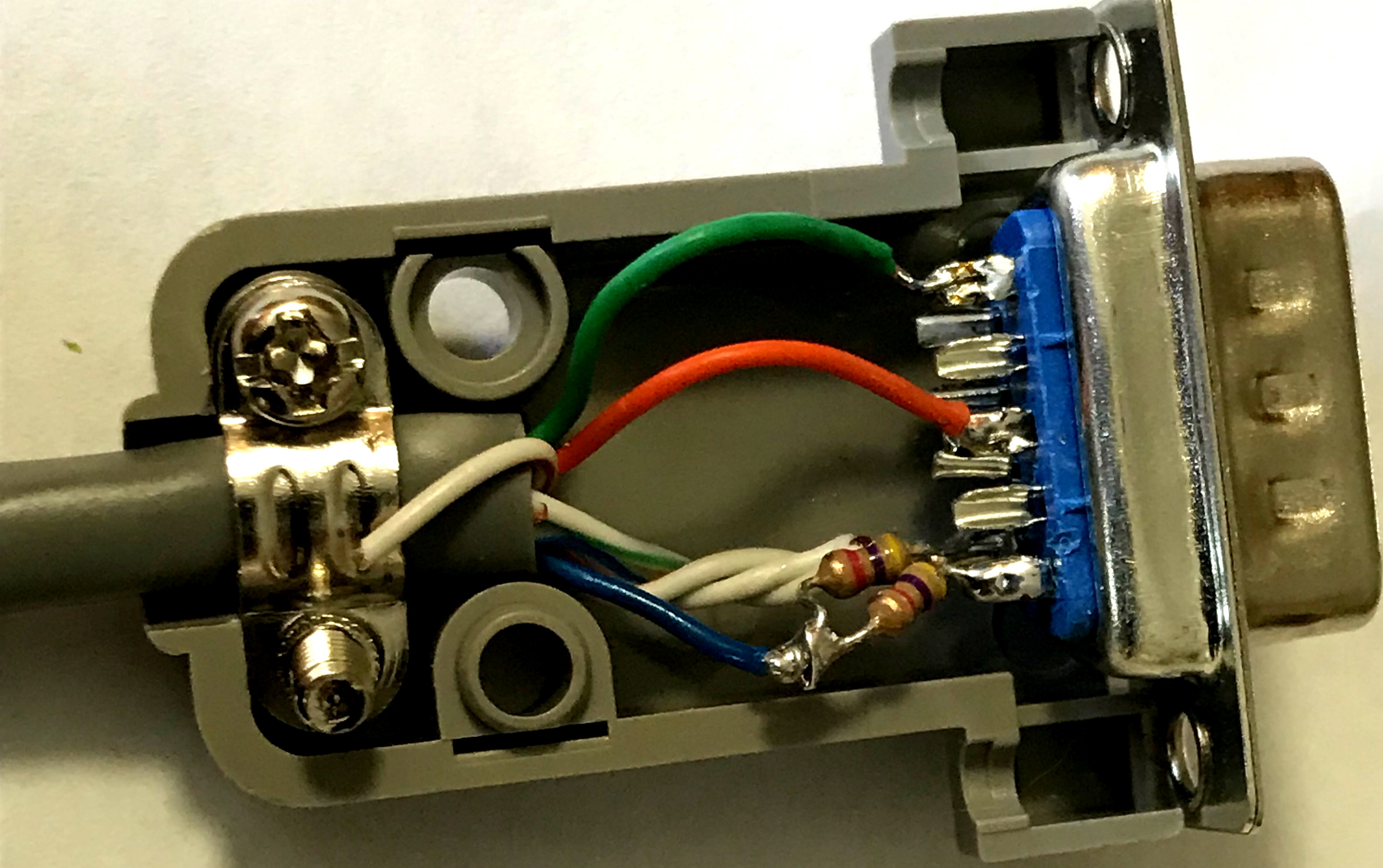
Strip the DE9 end of the cable back about 3/4 of an inch.
Cut the brown wire back to strip point.
Cut the green/white and brown/white wires back to the strip point.
We're not soldering those.
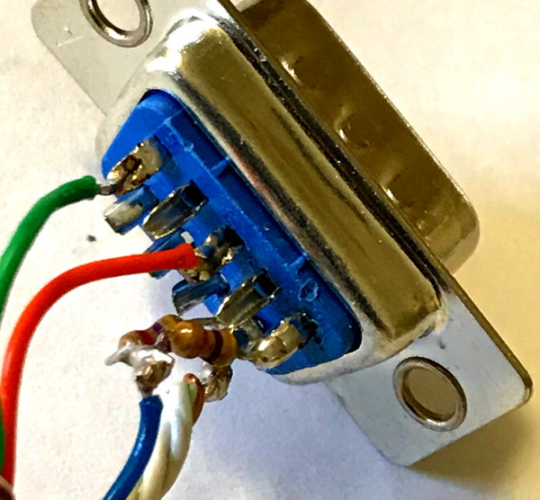
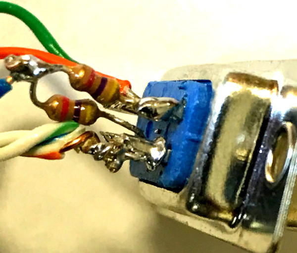
Twist the ground wires, BLUE/WHITE and ORANGE/WHITE, together.
Trim, and solder the pair of wires to pin 6.
Solder the Green and Orange wires to the DE9 connector pins 5 and 3 as shown earlier.
Solder the blue wire to the center/wiper pin of the POT, and then two outer pins of the POT go to 6-ground and 1-TxData.
The blue wire feeds the transmit audio to the TK radio.
For more information, consult
TNC and Radio Adjust and Test