Maxon SD-125 Programming Interface
Jim WB2LHP My email is good in
QRZ
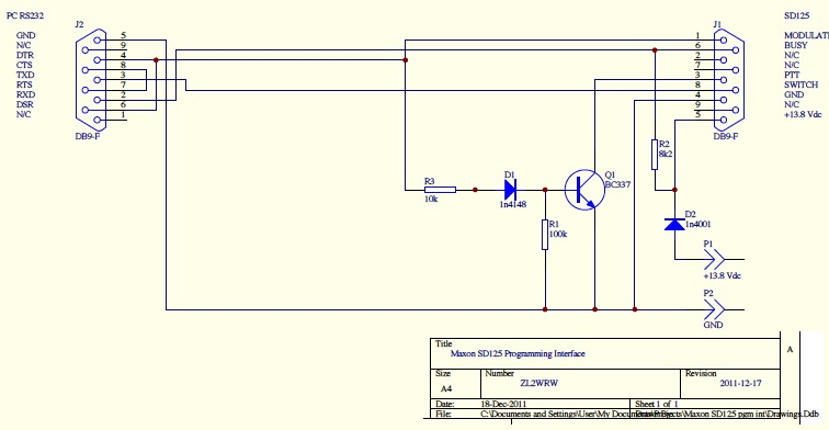
In order to program this unit you will need buy or build a programming interface.
The programming interface has two connectors, one which goes to your computer, and the other to the SD-125 transceiver.
The computer interface given in the schematic is RS-232 but you may connect that to a USB to RS232 adapter to attach to a modern MSWindows computer.
There is one very important item about the interface.
Even with the DTR/DSR lines connected per the diagram, my interface would not work with the software.
That is because (at least with my serial card) they never get driven high and consequently will not force the radio into the programming mode.
I fixed that by leaving the DTR/DSR lines tied together like the CTS/RTS lines are but left them isolated from the circuit.
Then I drove the junction of R3 and J1-1 with 12 volts through a 2.2K resistor.
That worked.
It could just be the way my serial card is.
Your mileage may vary.
Please keep that in mind.
Be sure to follow the programming sequence exactly as described.
There is a squelch adjustment but it requires a separate programming interface and software (go figure).
I have found the factory setting to work fine with no issues and would not recommend going down this rabbit hole.
This is the link to the
full Maxon SD-125 series service manual.
Schematic

Commercial Programming Cable
RFGUYS have a programming cable for $50 and that's here:
RFGUYS SKU 33111
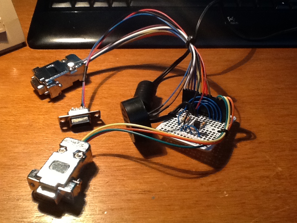
example of home-brew unit
This deviates from the schematic in a couple of ways.
The black round object is a speaker and it is wired to the extra un-hooded DB9 which is used for setting up the SD-125 as a monitor receiver.
At some point we'll build a programming widget which is purely the schematic, or draw our own schematic showing an improved widget.
 Back to Maxon Programming
Back to Maxon SD-125 page
