Maxon SD-125
Using the Maxon SD-125 Series Radios for TARPN
Jim WB2LHP My email is good in
QRZ
The Maxon SD-125 series radios are VHF and UHF data transceivers designed for and used by the water control industry to monitor fluid levels and flow.
Many of them have recently shown up on the surplus market at very reasonable prices.
These are 16 channel, switchable 1 and 5 watt transceivers that will cover the amateur VHF and UHF bands.
There are two common versions that are appropriate for use in the TARPN systems.
SD-125V2 148-174 MHz
SD-125U2 440-470 MHz
Testing has shown that the V2 radios cover the entire VHF band without adjustment and the U2 radios will go as low as 425 MHz without adjustment.
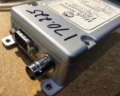
These radios sport direct 13.8VDC (9v to 15v) operation and have a built-in speaker amplifier.
They are fitted in a die cast aluminum enclosure, fully shielded and RF bypassed.
There is a DB-9 male wiring connector and a BNC female RF connector.
Performance in my testing has been excellent.
These radios are ideal for compact, short to medium hop systems.
This page addresses wiring to the TNC for operation.
We assume the radios have already been programmed.
If your radios are fresh from some other service, then click here:
Programming/no-Alignment.
Wiring of the radios is very straight-forward with connectons for TX audio, RX audio, PTT, SPKR, GND and +12VDC.
I have used unshielded wire with no issues.
These are all high level signals.
The TX audio goes directly to the varactor modulator and the RX audio comes straight off the discriminator, allowing for speeds up to 9600 baud with the appropriate modem.
Both the TX audio and RX audio are buffered.
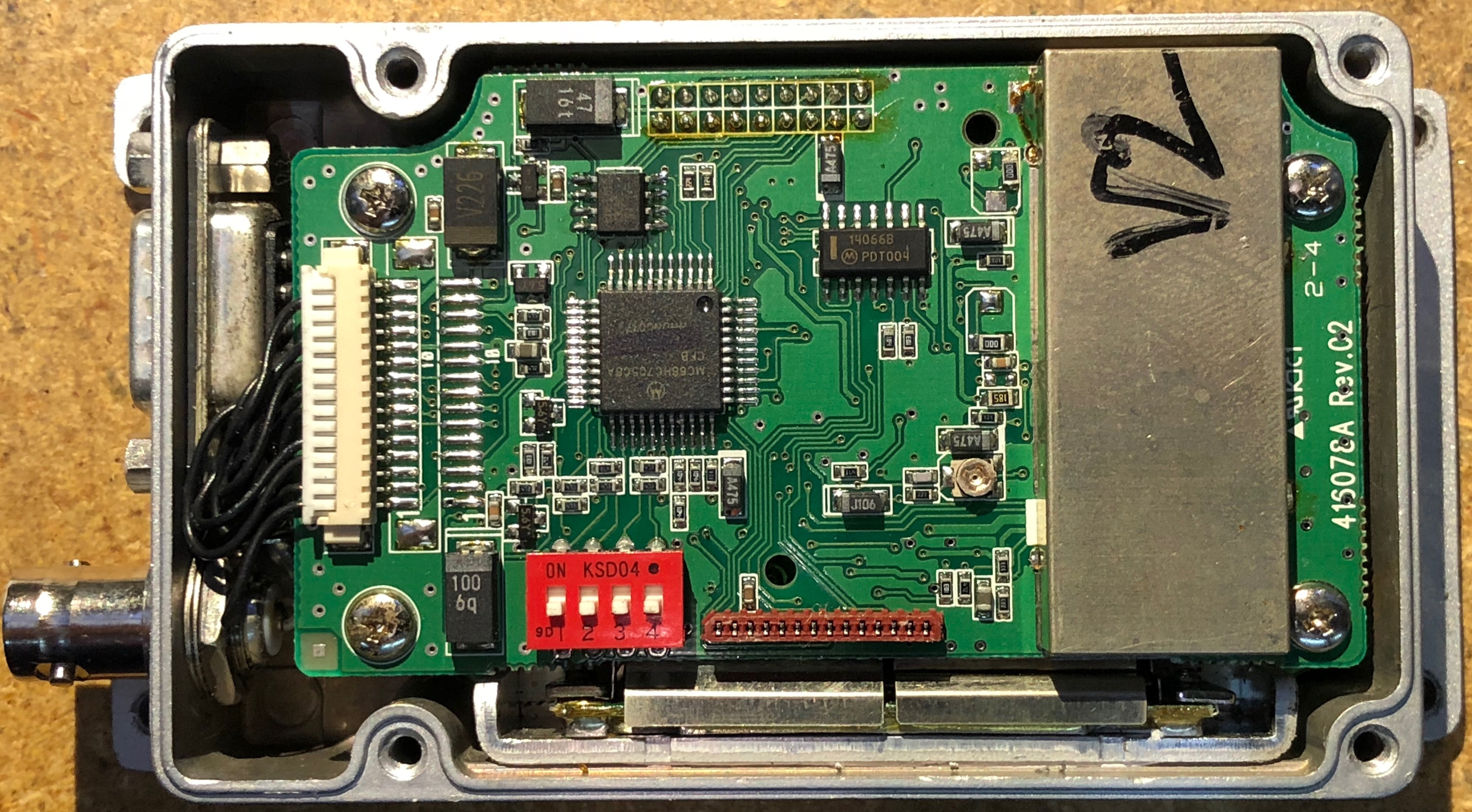
There is a squelch adjustment but it requires a separate programming interface and software (go figure).
I have found the factory setting to work fine with no issues and would not recommend going down this rabbit hole.
Making the TNC cable
If you’re using the TNC-Pi’s or Kantronics TNCs having the 9-pin Dsub connector then see this table.
Keep in mind that the pin number on the female connector is opposite of the male connector.
Use CAT5 wire. white/blue, white/orange, white/green wires can be twisted together at both ends for runs longer than a foot or so.
If wire length is short, just use white/blue for ground.
Solder a 16 gauge zip wire ground-side to pin 4 of the Maxon's DE9 female connector in addition to the white/blue wire.
This is power to the Maxon.
The hot side of the zip wire goes to pin 5 of the Moxon.
If you use thin zip cord, it will become too fragile.
We used 20 gauge and it went badly.
| Wiring Maxon to Kantronics or TNC-PI |
Signal | Maxon
female
pin | TNC
male
pin |
Wire
Color | |
|---|
| TX Audio | 1 | 1 | Blue | |
| RX Audio | 2 | 5 | Green | |
| PTT | 3 | 3 | Orange | |
| GND | 4 | 6 | white/blue + black | |
| VCC (13.8VDC) | 5 | | RED | |
| Monitor Speaker | 9 | | | |
This drawing is of the solder cups on the back of each of the radio-cable DE9s from the perspective of the inside of each D-sub Shell.
Click to embiggen wiring diagram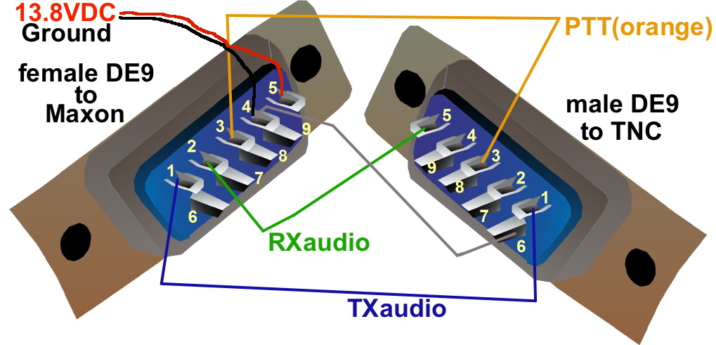
I used unshielded wires with no issue.
These are all high level signals.
The Speaker output is very handy for monitoring and level setting.
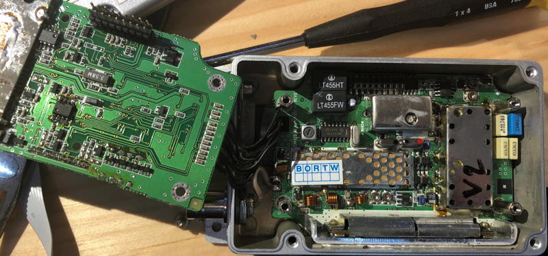
It is driven by a LM386 with plenty of volume.
You can adjust the speaker output level internally in the radio.
It is a very small pot next to the shielded assembly on the top board.
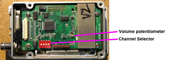

Aside from this one adjustment, there are no other adjustments that need to be made to these radios for them to perform properly.
Please feel free to email me at my
Jim WB2LHP on QRZ email address with any questions.
Click to embiggen