| home | builders | Search |
| builders ➜ Power Supply and Backup ➜ Power Manager project |
|
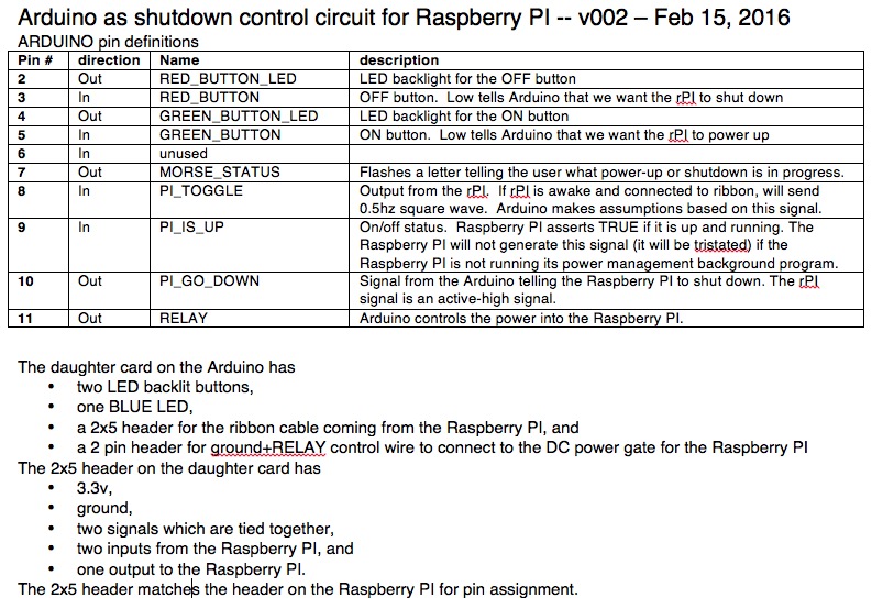
PWRMAN is a power controller for the Raspberry PI, designed with ham radio operators in mind.
It expects a 13.8volt environment common in ham radio installations and hamshacks.
PWRMAN provides automatic emergency shutdown in the case of power failure as well as automatic
power restoration when main power is restored.
Do you run a Raspberry PI powered ham system which must stay up unattended? Is Raspberry PI status (up? crashed?) sometimes a mystery in your station? Do you find it painful to power down the Raspberry PI while avoiding the pitfalls of sudden power removal? The PWRMAN supports a ham radio system where the Raspberry PI is a tool to perform a job, but is not run as a desktop computer. Usually we do not have the Raspberry PI screen up so operating SHUTDOWN is not convenient. |
|
There are several basic functions of the PWRMAN.
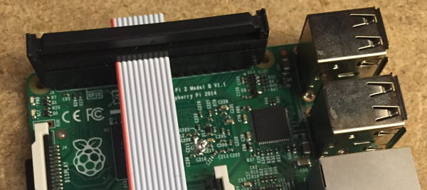
Connection between the PWRMAN and the Raspberry Pi uses 10 pins of the Expansion Connector. There are two easy ways to hook up the PWRMAN.
OR
|
|
|
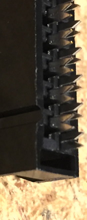
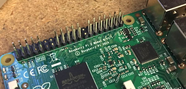
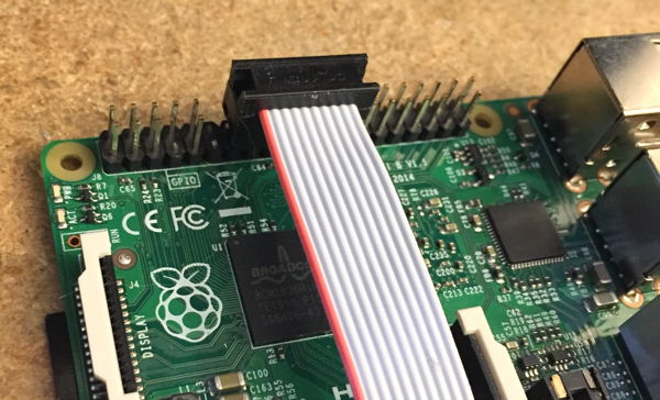
The photo, below, shows the modified Expansion Connector.
I cut seven pins on the Raspberry PI's connector.
Pins 11, 12, 13, 14, 25 and 26 were removed so the ribbon cable IDC connectors attach firmly.
Pin 7 was removed for the monitor speaker mod/audio monitor.
The drawing on the right shows the pin numbers with green boxes where the ribbon cables connect.
The upper connector is for the TNC-PIs.
The lower is for the PWRMAN.
Blue pin#s are the pins to cut and remove.
|
SDcard end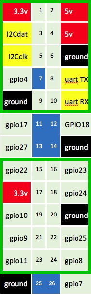
|
|
Final Assembly:
If you want to make these things, please contact us.
If you want to help make these things, please contact us.
Contact us through TARPN groups-io email reflector, or email if you have QRZ access.
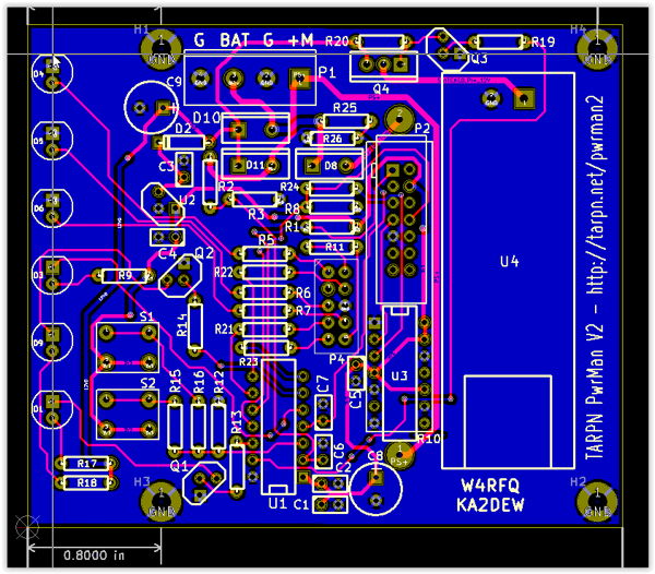
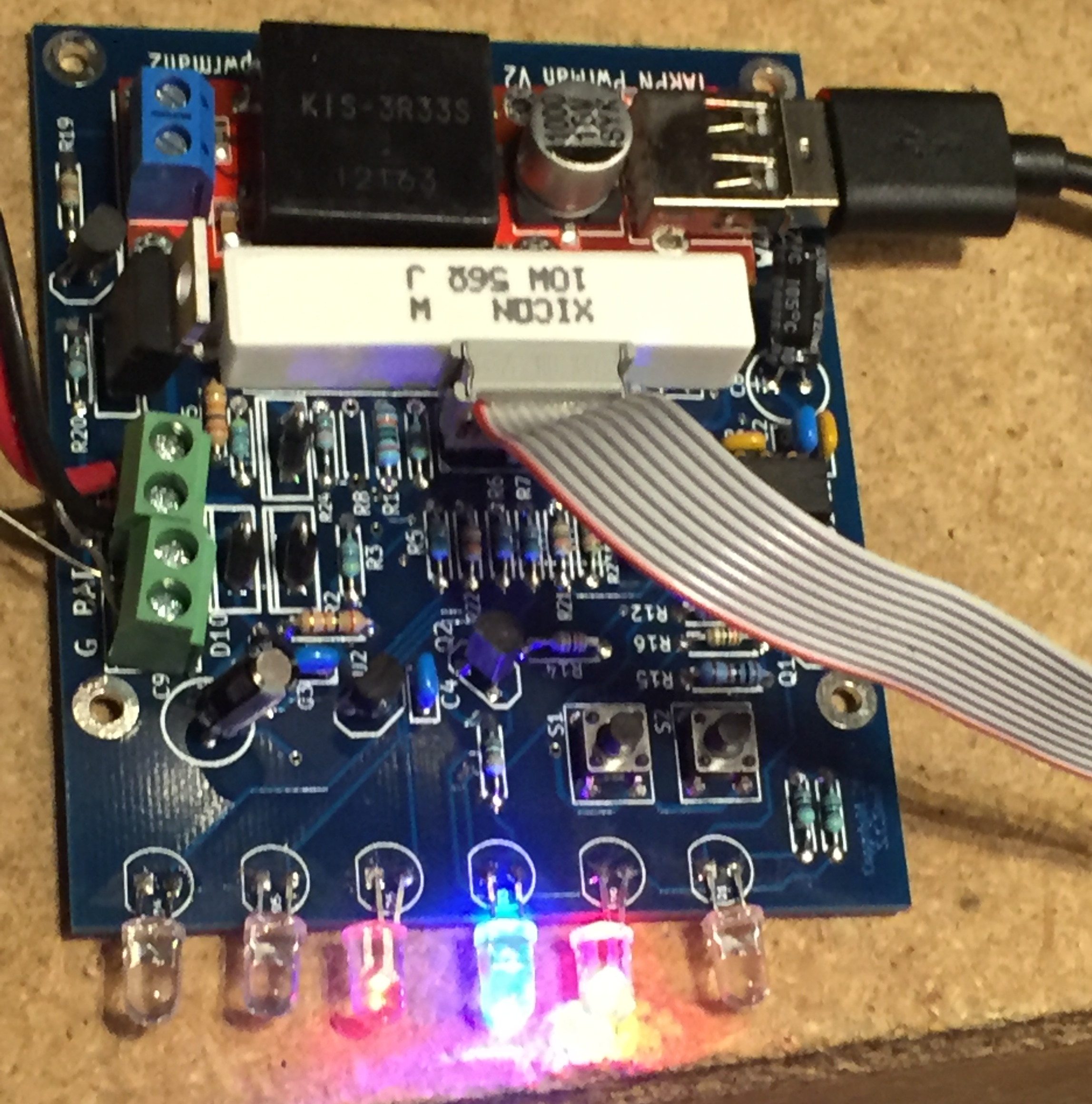
Our board has six LEDs and two buttons. Each button is associated with the nearby LED. From top to bottom the LEDs are:
U3 and the 14 pin socket are for development use and connection to the TI UIF-FET device. They do not need to be populated. When the board is fully assembled those two footprints are obscured by the 10watt 56ohm resistor R10.
U4 is a KIS3R33S USB adapter module available via eBay for under $2 delivered. It converts 7volts to 24volts DC to 5volts at up to 3amps and delivers it on a USB connector.
U1 is the TI MSP430F2012IN cpu. It's available for $2.02 from Mouser Electronics.
The problem is, you need it programmed with the PWRMAN code.
In order to do that you need an uncommon tool. Maybe it isn't so uncommon.
Stay tuned to this web page? Sign up for the TARPN groups-io reflector?
E -- LOW POWER OFF
•
Flashes a single dit every 5 seconds or so.
The Raspberry PI is off.
The PWRMAN is trying to stretch the life of the Gel-Cell by using very little energy.
Red button is ignored. Green button, if pressed, will cause the PWRMAN to complain by lighting the red LED.
EEEEE -- OFF
••••• (dots repeat indefinitely)
Main supply is good, Raspberry PI is powered down, or Raspberry PI is powered up and non communicative
Normally we get here because the user wants the Raspberry PI turned off.
The exception is that we can also be in this state if the PWRMAN can't talk to the Raspberry PI even though PWRMAN turned it on.
If the power supply goes away, we'll go to LOW POWER OFF.
Green button tells PWRMAN to bring up the Raspberry PI.
U -- Coming UP
••―
Raspberry PI is being told to start.
This mode is entered automatically if the we were shutdown due to power-loss, or if we were in OFF and the user pressed the green button.
While waiting for the Raspberry PI to start, the green LED is illuminated.
Buttons are ignored.
R -- Running
•―•
Main supply is good. Raspberry PI is running
The main power supply is good. The Raspberry PI is up and answering.
Red button will shut DOWN the Raspberry PI. Removal of main power will eventually shut DOWN the Raspberry PI.
If red LED is flashing, the main power is removed and the Raspberry PI will shut DOWN after 2.5 minutes.
Red LED will flash faster and faster as we get to the end of the 2.5 minutes.
If main supply comes back, cancel timer and stop blinking the red LED.
D -- Shutting DOWN
―••
Raspberry PI is shutting down.
This mode is entered by the user pressing the DOWN (red) button from OFF, or main power has gone away and not recovered after 2.5 minutes.
Red LED is illuminated as we tell the Raspberry PI to shut down.
Once Linux, going through shutdown, has closed the Power Manager Service, the PWRMAN starts flashing the red LED.
After a few seconds the PWRMAN will turn off the Raspberry PI's power, and then go to OFF mode.
Buttons are ignored in DOWN state.
The PWRMAN1 board has three DC connections, the main power supply at around 13.8 volts, a GelCel battery at 12 volts, and the Raspberry PI output which is at something higher than 6 volts and is used to run the KIS3R33S USB adapter. See Robust power for Raspberry PI.
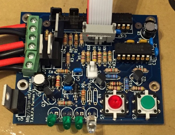
The two buttons will not be illuminated in our next version. We'll use separate buttons and LEDs. The illuminated buttons turned out to be too hard to get, too hard to work with, and the LEDs sometimes don't work.
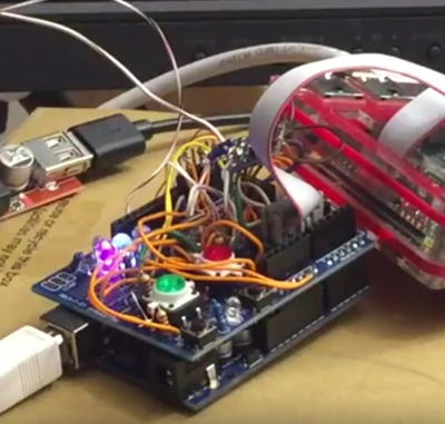
Here is a link to a movie showing my first prototype powermanager in use - February 2016.
I (KA2DEW) designed and hand-wired this on a daughter card for an Arduino.
I also wrote the Arduino "sketch".
See below for downloads and design notes.
Before even getting half way through the process of wiring up the Arduino I had decided to switch to the TI MSP430 CPU. I could have used one of the Arduino family of boards or Atmel chips in a more elegant configuration, like a PCB, and I had intended to, if only to promote people to consider my source code and use it to improve the PWRMAN or come up with more devices for our hobby. Arduino has a serious advantage over most other coding mechanisms because it is so easy to get started in. However, I was uncomfortable with the low power shut-down modes of the Atmel and desired to use the MSP430's micro-amp low power modes. It was my design requirement that the PWRMAN could watch the main power input and make its own decision to bring up the Raspberry PI when the main supply is restored. It was obvious to me how to do that with the MSP430, and less obvious with the Arduino. So I went with the familiar.
After finishing the Arduino version of the project I decided the TI MSP430F2012 would perform the hardware part of the project adequately. It was available in a through-hole form so we could still make a kit out of the project. Steve, W4RFQ, and I got together and decided we would build the entire thing with through-hole parts and work as though the project would become a kit.
As of June 2016 we're still planning to make a kit out of it but we haven't figured out who, when and where the process of bundling the parts together would take place, or who would sell the thing and take money for it, or even how we'd do that. We're considering using one of the crowd funding sites, and also considering just doing a paypal button.
Here is a link to a movie showing the second working model, labelled PWRMAN1.
This board was designed, laid-out, ordered, and stuffed, by Steve, W4RFQ.
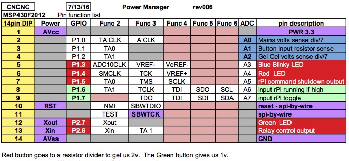
After Steve made the board based on my CPU pin-out diagram (see below) and stuffed it, tested it, calibrated the resistor values, he brought it over and I made my ported-firmware come up.
A couple of evenings later I filmed this movie of the unit in operation and then delivered the one working prototype back to Steve.
l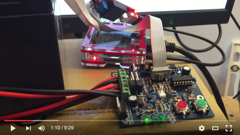
The TARPN packet radio installations include the power manager scripting and setup to talk to the PWRMAN boards. If you start up your TARPN Raspberry PI using the PWRMAN, the Raspberry PI will drive the three LEDs it controls. The buttons will now also be active, and the PWRMAN will report the status of the power management.
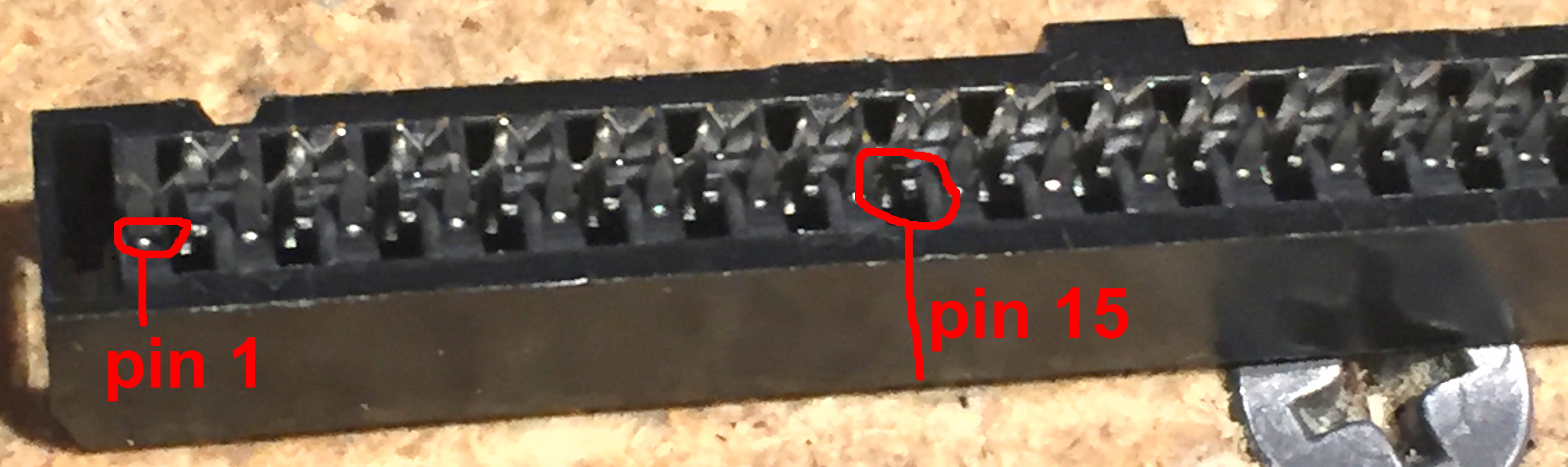
Pinout for the 10 pin ribbon cable from the Raspberry PI's side:
This diagram represents 10 of the pins on the Raspberry PI's expansion connector, where the ribbon cable to the PWRMAN is attached.
The text "SD-Card end" is trying to show the orientation of the connector. Pins 15 and 16 are on one end of the 10-pin set, and 23 and 24 are on the other.
The end of the 10-pin set that is toward the SD-Card is 15 and 16. See the drawing up above next to the Raspberry PI photos to see where on the 40 pin connector to find these 10 pins.
The out-to-LED gpios are routed across the ribbon cable to LEDs D4, D5 and D6 on the pwrman boards.
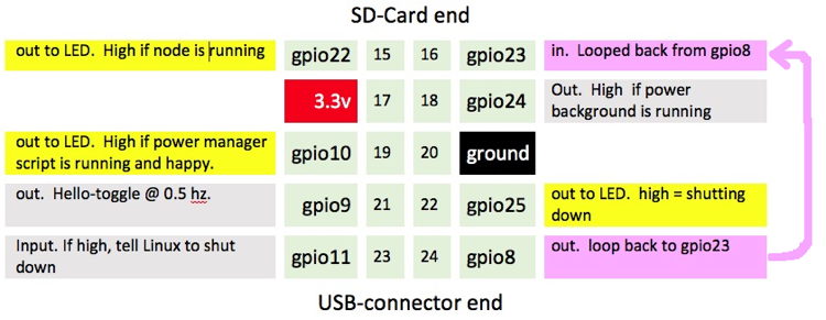
If the ribbon cable is properly connected on both the Raspberry PI and on the PWRMAN board, gpio8 from the PI drives out across the ribbon, through a resistor, and back across the ribbon to gpio23. In very short order the pi_shutdown_background script can determine that the PWRMAN board is, in fact, present and the ribbon cable connected correctly. If the PWRMAN board is not detected, the script will stop driving all of the GPIOs under the ribbon cable connector and will ignore any signals seen, for 15 minutes. Every 15 minutes it will try again to see if the loop-back through the ribbon cable is working.
A log file is created and written-to every time an error occurs at the pi_shutdown_background script, including each time the loop-back fails, i.e. every 15 minutes. That file lives at /usr/local/etc/pi_shutdown.log Under worst case conditions (no PWRMAN found) that log file will grow by 8 megabytes per year.
I put together a code package representing the script and background service configuration for the Raspberry PI under Debian Jessie. For the TARPN packet radio users I embedded this code as part of the TARPN code distribution and automatic updater system. If you are interested in running the PWRMAN with your own Raspberry PI application, you'll need to replicate this. I have a zip file containing the script I am using, and the service configuration file I'm using. The installer script and updater I'm using would have to be dissected in order to build a stand-alone non-TARPN mechanism. I did some of that dissection myself and am providing that as part of the r-pi-script-and-support zip file below. The install service script is untested.
I'm hoping some nice Linux/Raspberry PI community member will take on the task of making a apt-get packet manager version of this project.
If you get that script to work, or make any improvements, I'd appreciate the help. My email address is on QRZ for KA2DEW.
Click here for the Raspberry PI BASH script and support code.
Click here for MSP430 source code for PWRMAN2: PWRMAN2 V4 Sourcecode
MSP430F2012 pinout
Click here for the Arduino sketch ("sketch" is what source-code is called in the Arduino dev program).
Below are the notes I wrote to describe the Arduino end: