| home | builders | Search |
| builders ➜ TNC-PI ➜ TNC-PI Kit Ordering and Assembly |
| The TNC-PI is discontinued. Support for TNC-PI is no longer expected to work on Raspberry PIs set up for TARPNs. The TARPN project created the NinoTNC as a replacement for the TNC-PI. NinoTNC is easier to build (as a kit), more powerful, easier to configure, easier to operate. I'm leaving these TNC-PI pages intact, but the tools and commands referenced here only exist because they didn't get in the way, much. Some elements will disappear from the TARPN tools over the next several years. Please check out the NinoTNC at TARPN hardware projects documentation. |
|
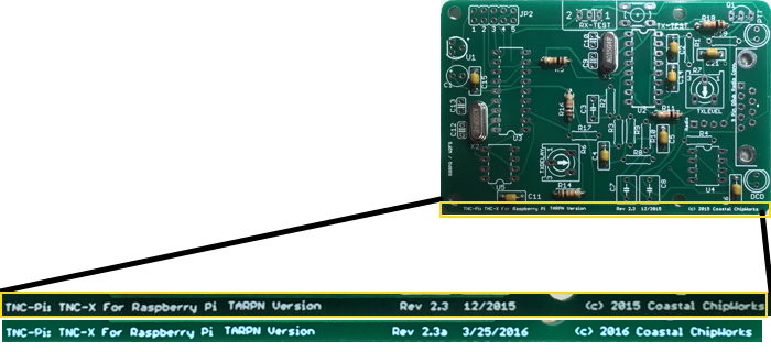
Coastal Chipworks says "Thanks for all the fish" -Douglas Adams and they are closing their doors. The good news is they made a bunch of fine products and made it possible for us to create cheap packet networks. The other good news is they gave us time to make the NinoTNC. The bad news is we didn't have quite as much time as we'd have liked to fully develop NinoTNC and the support network for it. |
|
|
I suggest you use a temperature controlled soldering iron, and rosin core lead solder, 60/40 or some such. Also, don't use flux on the board. Cleaning the board before or after soldering should not be necessary.
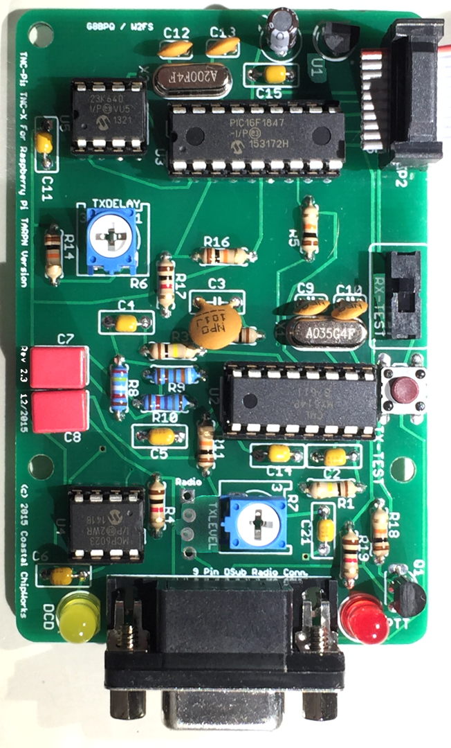
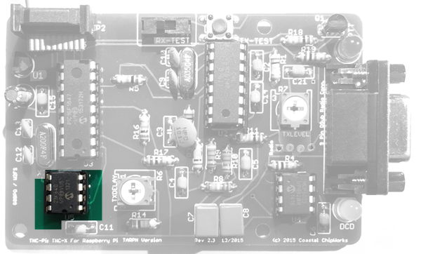
| ⇒ The part designations, like R1, U2, etc... are silkscreened on the top of the board. Insert all parts from the top of the board where the appropriate designator indicates. The photos provided may be helpful. |
| ⇒ If there is a step which installs multiple parts, you can put all of the parts into the board in any order, and then solder all of them at once. |
| ⇒ The reason for the step–wise assembly order is so in each step when the board is flipped upside–down for soldering the board doesn't rock too much, and for some steps you can take advantage of the table–top to force the parts flush to the board for best mechanical stability. The test step, to assure proper voltage regulator function, is done as early as convenient. |
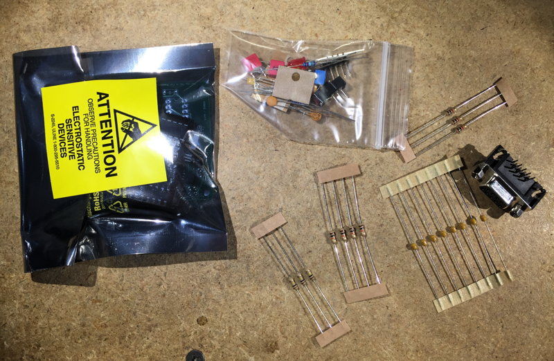
What you will need
|
|
Some of the images on this page can be enlarged and opened in a new browser tab by clicking on them.
| ⇒ All parts are inserted from the silk-screened side of the board, i.e. from the side on which the white writing is printed. |
| ⇒ Except where specifically noted, all two pin components are non-polorized so you can put the part onto the board with the pins in either hole. |
| 1 | X1 | 3.57 MHz crystal

 |
The crystal will have some code on it containing the numbers 035 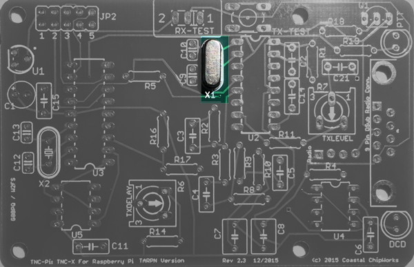 |
| 2 | X2 | 20.00 MHz crystal
|
The crystal will have some code on it containing the numbers 200
Note: Make sure you place X2 into the PCB spot marked for it. There is a capacitor part which is the same footprint and adjacent to the crystal. 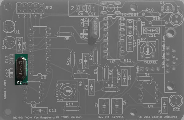 |
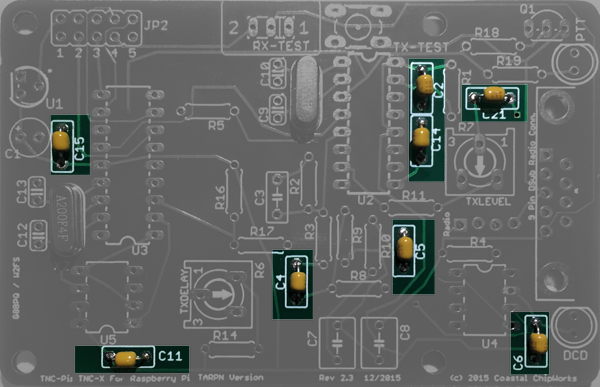
| 3 | C2, C4, C5, C6, C11, C14, C15, C21 |
0.1 f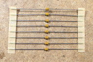 |
Eight yellow non-polorized barrels
|
| 4 | R5, R11, R14, R16, R18 |
10K resistor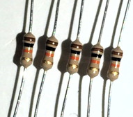 |
Brown, black, orange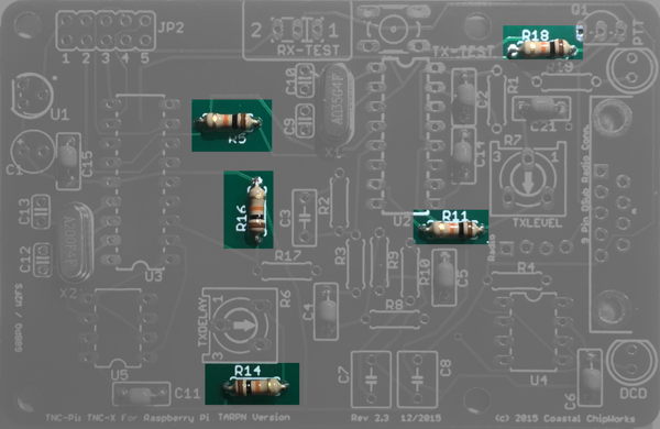 |
| 5 | R1, R2, R3 | 100K resistor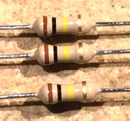 > > |
Brown, black, yellow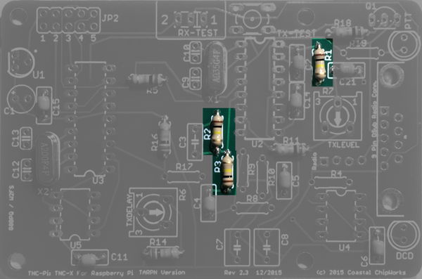 |
| 6 | R4, R17, R19 | 1K resistor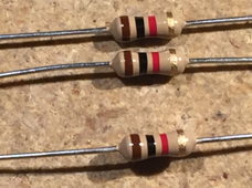 |
Brown, black, red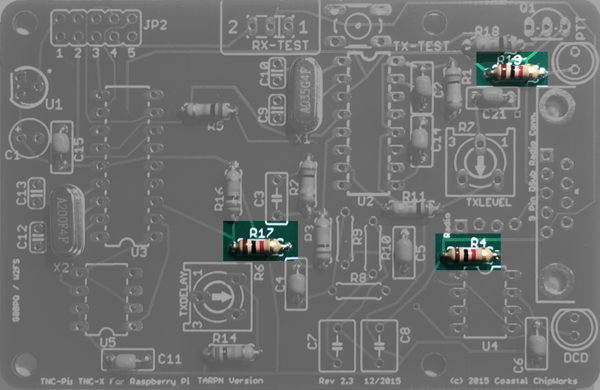 |
| 7 | R8 | 24.9K resistor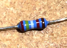 |
Red, yellow, white, red, brown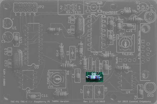 |
| 8 | R9 | 9.31K resistor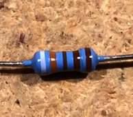 |
White, orange, brown, brown, brown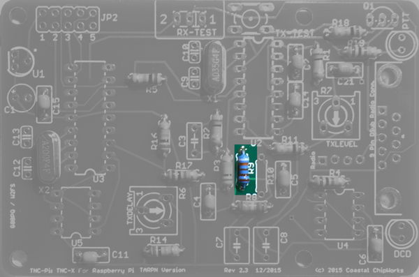 |
| 9 | R10 | 18.7K resistor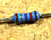 |
Brown, grey, purple, red, brown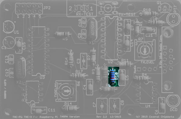 |
| 10 | U2, U3 U4, U5 |
IC Sockets One 16-pin, one 18-pin and two 8-pin sockets 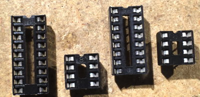 |
These are usually installed and soldered one at a time.
You can either hold the socket with a finger
while soldering the two corner pins in, then finish the rest of the pins, or you can insert the socket and then bend out two
of the corner pins to hold it into place.
Be careful of the orientation. They are not all pointing the same way! 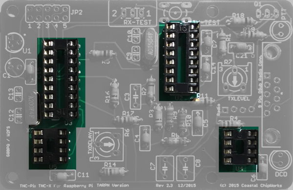
|
| 11 | TX TEST | pushbutton, 4-pin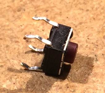 |
Carefully wiggle the four pins through their holes.
Don't put excess pressure else they bend and are hard to put back.
The switch is not square. Rotate the switch so the pin cups are pointed left and right across the board. 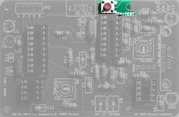
|
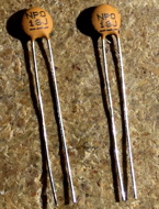
| 12 | C9, C10 | 18 pf
 |
ceramic disk
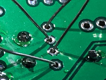
⇐ When stuffing the capacitors, direct the wires so they don't cross. This will enable you to solder the pads without shorting. |
| 13 | C12, C13 | 22 pf

|
ceramic disk
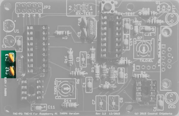
⇐ When stuffing the capacitors, direct the wires so they don't cross. This will enable you to solder the pads without shorting. |
| 14 | C7, C8 | 0.01 f 2.5%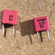 |
Red and yellow or grey; if grey marked 10 nF
While non polorized, these parts are not symmetrical. There is one orientation where the two parts won't fit side by side. Rotate the two parts individually so they both fit snuggly against the board, then bend the leads apart, and then solder. 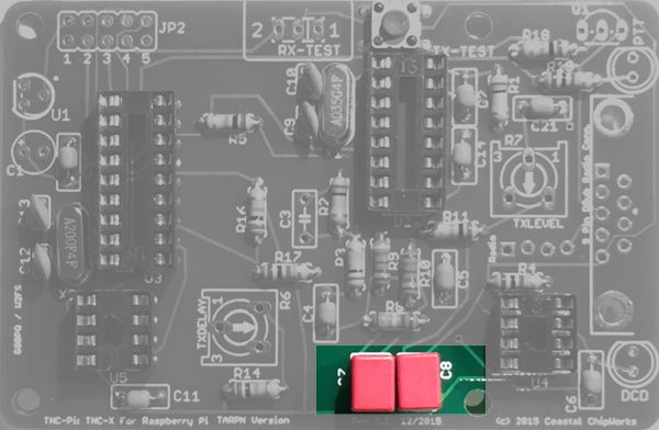
|
| 15 | C3 | 100 pf
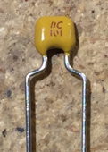
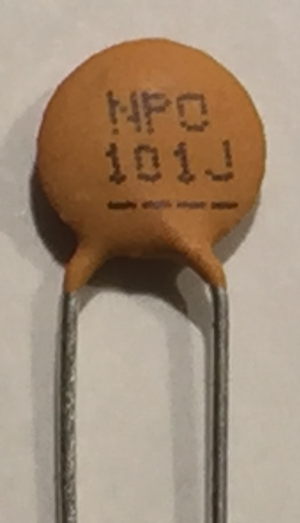 |
labelled 101 ceramic disk or dipped 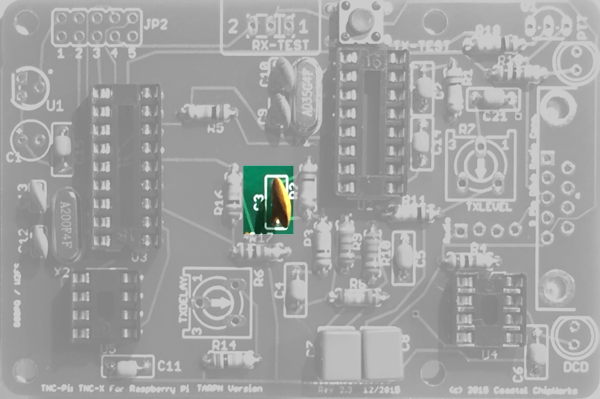 |
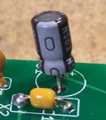
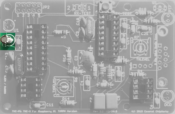
| 16 | C1 | 10 f Polarized electrolytic capacitor 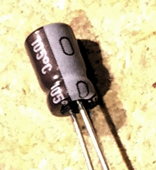
| Part has stripe on one side with ‑ sign. The other side lines up with + sign in the silkscreen. 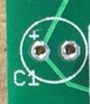
|
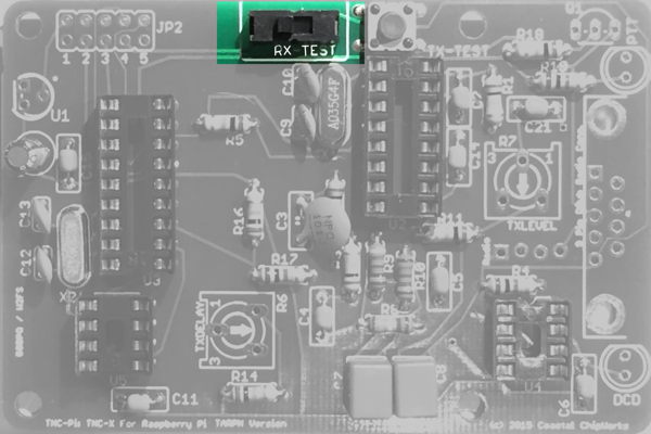
| 17 | RX TEST | SPDT
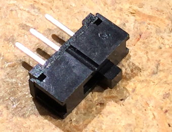 |
slide switch, 3-pin. Orientation doesn't matter.
|
| 18 | Q1 | PN2222 transistor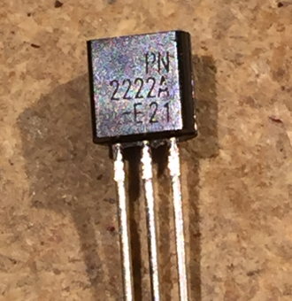 |
3-pin orientation is important! Line up part with silk-screen. Do not confused with U1 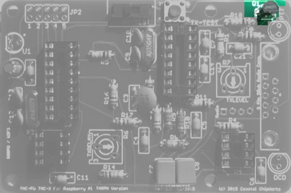 |
| 19 | U1 | Regulator MCP1700-3302E
or MCP1700-3002E 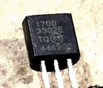 |
3 pin orientation is important! Install so the flat side is toward the edge of the board. 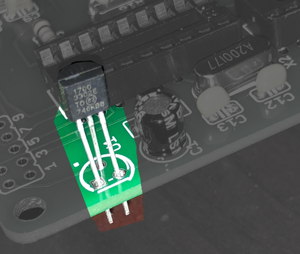 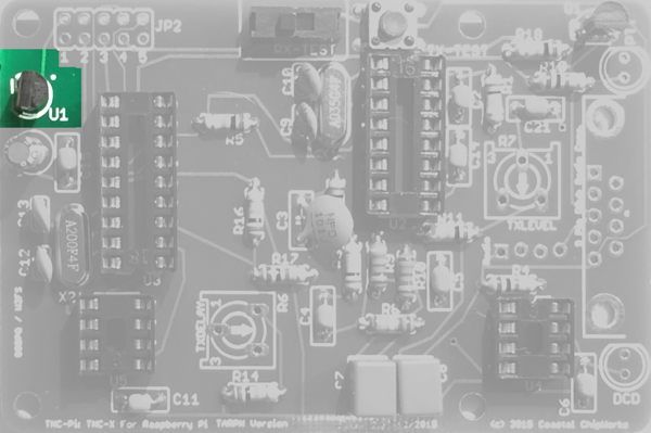
|
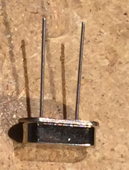
| 20 | JP2 | 2 x 5 header
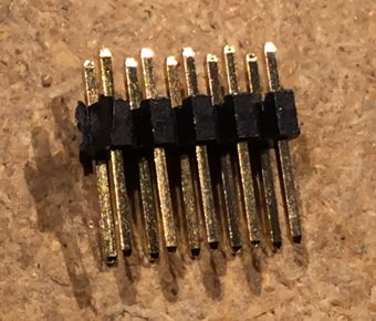
 |
Insert on top, solder from bottom
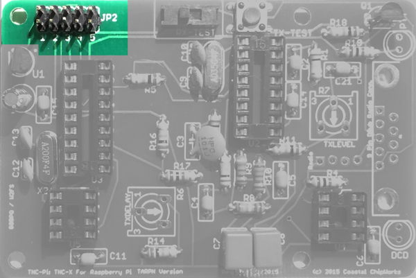
Short pin goes down through the board. Long pin side is up. See pic on left. |
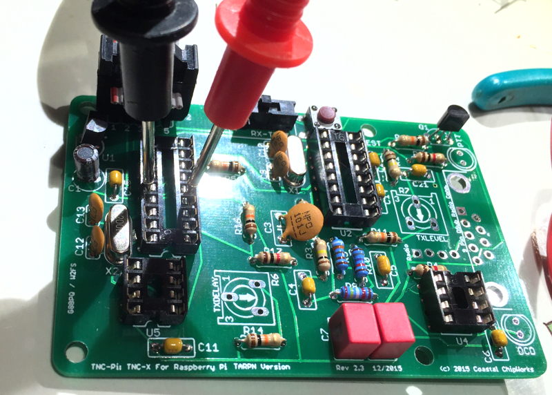
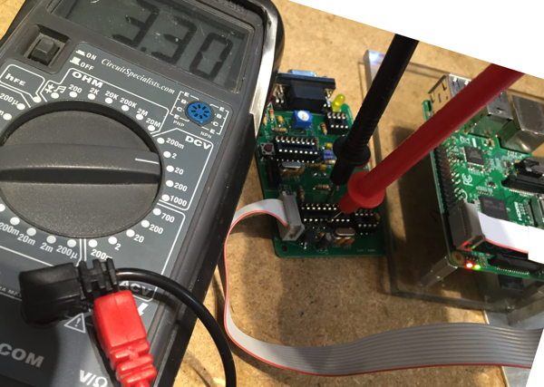
| 21 | Power up and test voltage |
| 22 | D5 D4 |
Yellow LED (DCD)
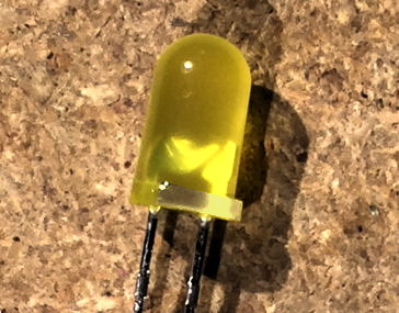
Red LED (PTT) 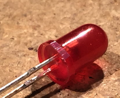 |
Orientation is important!
Notice that the LED silkscreens show a flat side. Make sure the squared end of the LEDs line up with the silkscreen. Ensure the shorter leads on the LEDs go through the holes closest to the flat side of the LED outline. 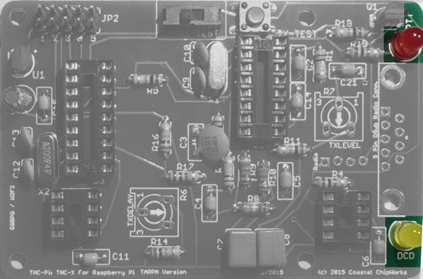 |
| 23 | R6 and R7 | 10K trimmer potentiometers
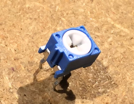 |
Orange or blue and white
Carefully wiggle the three pins through their holes. Don't put excess pressure else they bend and are hard to put back. Using a screwdriver, set the potentiometers to about the middle of their range. A feature of the TNC-PI uses R6 TXDELAY to erase the I2C programming. If R6 is set fully counter-clockwise (off) when the TNC-PI is reset or powered up, the TNC-PI will erase its I2C address programming. Set both potentiometers to middle until the Configure TNC-PI process! 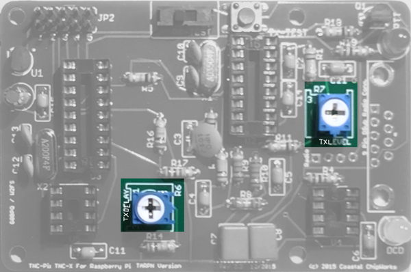 |
| 24 | DE-9 connector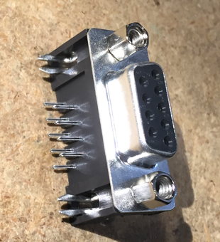
|
Push flush to the board.
Solder the 2 large pin-pairs on the side holes first while forcing the connector solidly onto the board.
This will give you the most robust connector. Next solder the 9 small pins. 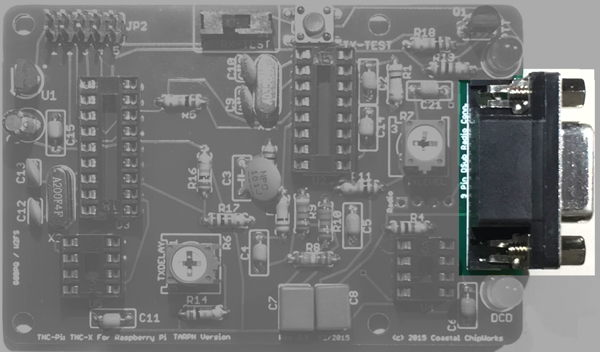 |
|
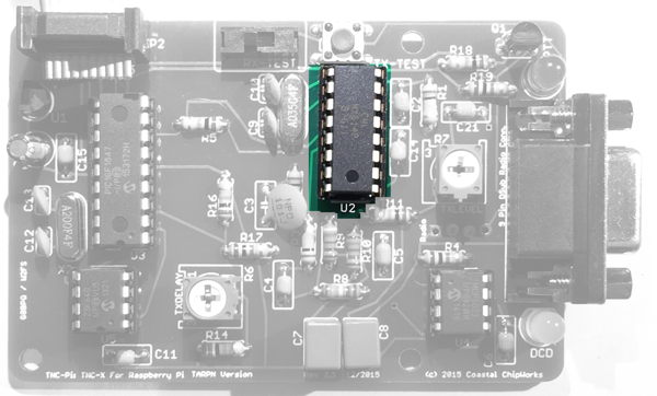
You may wish to bend the pins of the four ICs slightly inward to facilitate inserting them into their sockets.
Ensure the notch on the top of each chip lines up with the notch printed on the PC board. Also make absolutely certain that you do not mix up the two 8 pin chips and plug them into the wrong sockets. |
|||
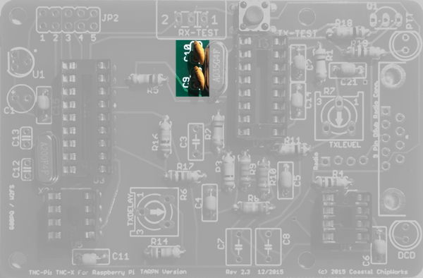
| 25 | U2 | CML MX-614 Modem
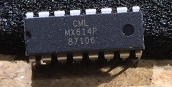 |
16 pin IC
|
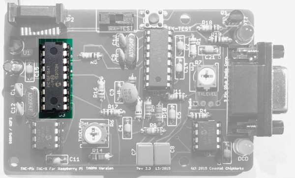
| 26 | U3 | PIC16F1847 microcontroller
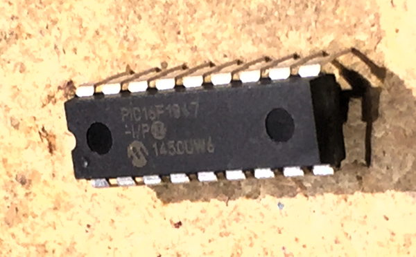 |
18 pin IC
|
| 27 | U4 | MCP6023 Op Amp
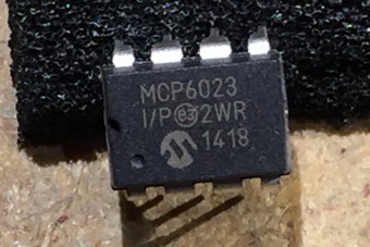 |
8 pin IC
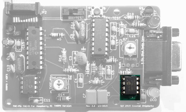 |
| 28 | U5 | 23K640 Memory
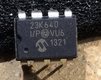 |
8 pin IC
 |
| 30 | Power up CPU test |
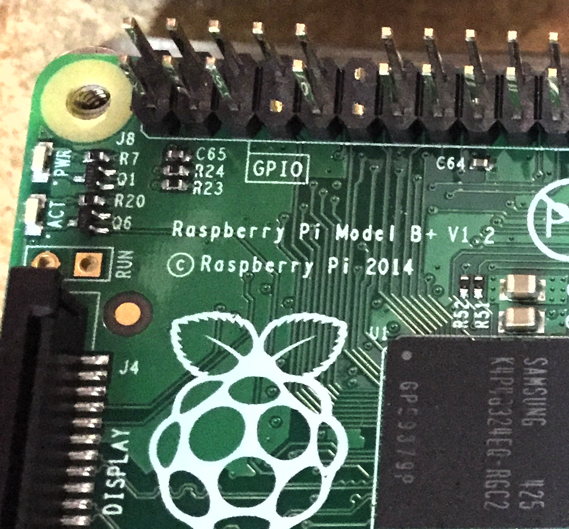
Connect up the TNC-PI ribbon to the Raspberry PI, observing proper ribbon polarity.
While observing the the LEDs on the TNC-PI, apply power to the Raspberry PI. The RED and YELLOW LEDs should both illuminate, then the RED goes off, followed by the YELLOW. Some additional flickering may also be observed after the two LEDs first go out.