This document is under construction.
Last modified by Tadd - Feb 14 2018
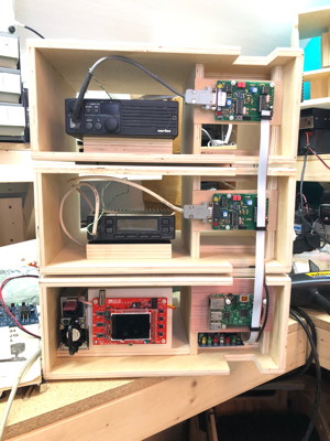
Box7 - 2018 Node Box Mod Stack
This box is custom made for expandable TARPN Nodes.
It is called the “Mod” box because you can start with just two and add as many more as you need.
Also, the Base box (containing the power supply, Raspberry-Pi, fuse box, ground block, and PowerMan board) and the
radio box (containing radio and TNC-Pi) are only different in small ways.
This design is currently the 7th box design and the 4th I’ve designed.
It is the result of many steps of trial and error, so deviate at your own peril.
Note that in these instructions, all directions are from the perspective of looking at the box from the front.
Purpose of the Node Box Mod Stack
The cabinet set is intended to
- maximize expandability of the node, i.e. adding another radio/link
- keep the equipment safe during modifications and upgrades
- show all controls and adjustments to the front to make it easy to fine tune the settings
- see the necessary read-outs
- provide optimal access to the components
- give adequate ventilation to move heat away from the radios
- allow swapping of radio+TNC assemblies to ease
- upgrading,
- testing, and
- verification
Description of the Node Box Mod Stack
The system consists of a base box and one or more radio boxes.
Each base box has support for
- main power supply
- Fuse box for power distribution
- Ground bus for power distribution.
- Raspberry PI
- Oscilloscope for readout of TNC-PI input audio
- Audio amplifier for TNC-PI audible monitoring
- 5v USB supply for Raspberry PI
- 9v supply for Oscilloscope
- backup battery
- backup supply switchover circuit
- speaker for TNC-PI/radio monitoring
- speaker for Raspberry PI output, used for incoming connection announcements and other features
Each radio box has support for
- large mobile transceiver
- TNC-PI
|
|
Details of the Node Box Mod Stack
There are components which have become popular in the TAPRN design but which are not specific to the intent and purpose of the TARPN.
The only parts which are specific to the intent and purpose are the Raspberry PI and that there are multiple radio/TNC sets.
The rest of the parts are those things which are cheap and available today.
The node stack box is designed to allow easy placement and access to the parts which are cheap and available today, as well as supporting the Raspberry PI.
Parts which are in vogue in early 2018 and to which the Node Box Mod Stack has been optimised:
- TNC-PI
- HP DPS1200FB power supply
- DSO138 oscilloscope
- 25 watt to 45 watt mobile 2-way VHF/UHF radio transceivers found on the surplus market, or ham radio mobile monoband VHF/UHF radios.
There are several major parts of the boxes.
| Top Panel | This is a rectangular piece of 1/4" plywood on top of each box.
The box which sits above this Top Panel will fit perfectly such that it won't slide off.
The footpads on the bottom of each box fit perfectly around the Top Panel of the box below.
We may be able to get the TARPN logo etched into the Top Panel which will look really great.
|
|
| Center-divider | A structural member is located between the left and right chassis and runs from near the front of the mod-box to near the rear.
The center-divider serves as a mount for the Raspberry PI/TNC-PI plate, as structure to hold the roof of the box up, and also as an air-flow guide.
|
|
Right chassis | The Right chassis is 4-3/4″ wide.
On the front of the box a plate presents the Raspberry PI or a TNC-PI.
The ribbon cable from these units goes up and down the stack of boxes
through a cut notch in the front top and bottom edges of the box.
The cable from the TNC-PI to the radio exits to the left across the front of the radio box.
The plate for mounting the board is across the middle of the space leaving room above and below for both airflow,
and access for running wires to the Raspberry PI and to the PWRMAN board which may be plugged into the Raspberry PI as a daughter/shield card.
A fan may be located near the rear of the right chassis, blowing forward.
If the mod box was placed against a wall blocking the rear, the Center Divider would permit air blown through the fan to be drawn over the radio or power supply, providing excellent cooling.
|
|
| Left chassis | The Left chassis is 8-1/2″ wide.
The primary feature of the left chassis is an 8-1/2″ wide slide-in pan which is of one of two depths.
The side-in pan is placed into the left chassis from the rear and is slid up under the rails until it strikes the front pan block.
For the radio version of the mod box the pan is !!!FIX!!! 3″ deep and has a block on top onto which a radio is Velcroed.
For the Base-Box version of the mod box, the pan is 9″ deep and has a plate in the front onto which the DSO138 oscilloscope is mounted.
The 9″ deep pan is perfect for mounting power supplies, fuse distribution, and other peripherals.
Both pans are removable and are held in by Velcroed accessories located toward the rear of the box, and which keep the Pan from sliding backwards.
|
|
|
Materials List
- 4′ x 8′ sheet of 1/2″ sanded plywood primed on one side.
I use Lowes Top Choice Blondewood 1/2-in Whitewood Plywood ($37). HERE is a link.
I get Lowes to cut it in half for easier 4′ x 4′ transport dimensions.
- 4′ x ‘4 (maybe less) of 3/16″ (5 mm) sanded plywood primed on one side ($15). I buy a full sheet and it lasts many boxes. HERE is a link.
- 3’ stick of 3/8″ pine dowel
- Good wood glue
- 3/4″ 23 gauge pin nails (if using pin nailer)
- 1/2″ 23 gauge pin nails (if using pin nailer)
- (8) 3/8″ 4-40 standoffs - for base box
- (8) 1/2″ 4-40 screws - for base box
- (8) 4-40 nuts - for base box
- (4) 3/8″ 4-40 standoffs - for each radio box
- (4) 1/2″ 4-40 screws - for each radio box
- (4) 4-40 nuts - for each radio box
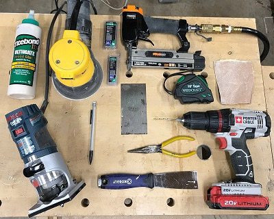
Tools Needed
- Table Saw
- Drill press with 3/8″ bit
- Scroll saw or Band Saw or Coping Saw
- Handheld trim router with 1/4″ rounding overbit, OR sand as desired
- Palm sander OR hand-sand like crazy
- Handheld drill with 1/8″ bit
- 23 gauge pin nailer with 3/4″ and 1/2″ pin nails OR use clamps to hold parts after gluing
- Needle nose pliers to pull out pins
- Putty knife for prying apart blocks
- Hand scraper for scraping glue out of corners
- Fine-tip pencil for marking
- Tape measure
- 120 or 150 grit sandpaper
Cut Diagrams
4′ x 8′ sheet of 1/2″ plywood
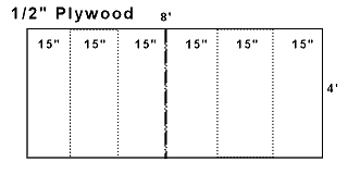
Each 15″ x 48″ piece gets cut again. --
Note: picture shows major cuts only
Jigs
Note: Jigs are supplied by Fin and may be freely replicated for your own use. Each cabinet-maker needs just one set.
The Jigs are labelled and called out during the construction process.
The Jigs have a letter which can be used to inventory them during clean-up.
1/2″ plywood
| A | Front Edge Jig | 13-3/4″ x 1-3/4″ |
| B | Back Edge Jig | 13-3/4″ x 1-3/4″ |
| | Edge scrap Jig | 5″ x 3/4″ |
3/16″ plywood
| C | Drill Template Jig | 5-1/4″ x 3″ |
| D | Front Corner Jig | 1-1/2″ x 3″ |
| E | Front Slot Jig | 2″ x 1-3/4″ |
| F | Back Corner Jig | 1-1/2″ x 2″ |
| G | Back Slot Jig | 1-1/2″ x 1″ |
| H | Top Panel Jig | 10-3/4″ x 7-3/4″ with a 1-5/16″ square removed from each corner. Mark the exact center along the front and side edges of the panel.
|
| I | Top Panel sizer Jig | 2″ x 13″ |
| J | Top Panel sizer Jig | 2″ x 13″ |
| K | Board panel sizer Jig | 6″ x 7/8″ |
| L | Circuit board holes Jig | 5-1/4″ x 2-1/2″ |
| M | O-scope panel holes Jig | 5-1/4″ x 4″ |

Instructions for building the TARPN Mod box
Step 1: Making the wood cuts
| 1 | |
Starting with a 4′ x 8′ of 1/2″
Birch plywood, cut the long dimension into 15″ sections.
Each of the 6 pieces will be 48″ x 15″ and each of these should make one box. |
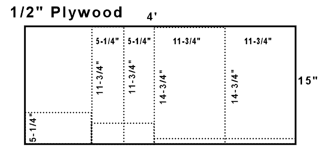
| 2 | | From one of these pieces, make the following cuts: |
| | a | Long-ways, make a cut at 11-3/4″ to make a piece 11-3/4″ x 15″ will be box-roof |
| | b | Long-ways, make a cut at 11-3/4″ to make another piece 11-3/4″ x 15″ will be box-bottom |
| | c | Long-ways, make a cut at 5-1/4″ to make a piece 5-1/4″ x 15″ will be left-side |
| | d | Long-ways, make a cut at 5-1/4″ to make another piece 5-1/4″ x 15″ will be right-side |
| | e | Turn the remaining piece 90 degrees and make a 5-1/4″ cut to make a piece 5-1/4″ x 13-1/2″ will be center-support |
| 3 | | Make the following cuts to create the designated parts common to both types of boxes: |
| | a | Cut the 15″ length from step a above to 14-3/4″ to make the box-roof |
| | b | Cut the 15″ length from step b above to 14-3/4″ to make the box-bottom |
| | c | Cut the 15″ length from step c above to 11-3/4″ to make a left-side |
| | d | Cut the 15″ length from step d above to 11-3/4″ to make a right-side |
| | e | Cut the 13-1/2″ length from step e above to 6-3/4″ to make the box center-support of 6-3/4″ x 5-1/4″.
Also cut a 3/4″ piece from what is left over to create the front right edge vertical support of 5-1/4″ x 3/4″
|
| 4 | | If working on the base box, cut the remaining parts to make the following: |
| | a | 9″ x 8-1/2″ base-sled |
| | b | 5-1/4″ x 4″ o-scope panel |
| | c | 5-1/4″ x 3/4″ o-scope panel brace |
| 5 | | If working on a radio box, cut the remaining parts to make the following: |
| | a | Two 5-1/4″ x 3″ parts to make the radio-block
|
| 6 | | From what is left over, cut the two 4-3/4″ x 3″ floor and ceiling supports |
| 7 | | From a 1/4″ sheet of plywood, cut the following parts: |
| | a | 10-3/4″ x 7-3/4″ top panel |
| | b | 5-1/4″ x 2-1/2″ circuit board panel |
| | c | Four 1-1/4″ x 1-1/4″ footpads |
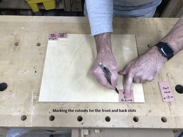
Step 2: Drawing the slots
| 1 | | Place the Front Corner Jig on the right front corner of the box top.
Make sure it aligns to the front and side edges.
Place the Front Slot Jig just to the left of the corner jig and make sure it is aligned to the front edge.
Press down on the slot jig so it doesn’t move, remove the corner jig, and draw a line around the 3 edges of the slot jig. |
| 2 | | Perform the same procedure to the right front of the box bottom. |
| 3 | | Perform the same process with the back left corner of both box top and bottom using the two jigs designated for the back corner and slot.
|
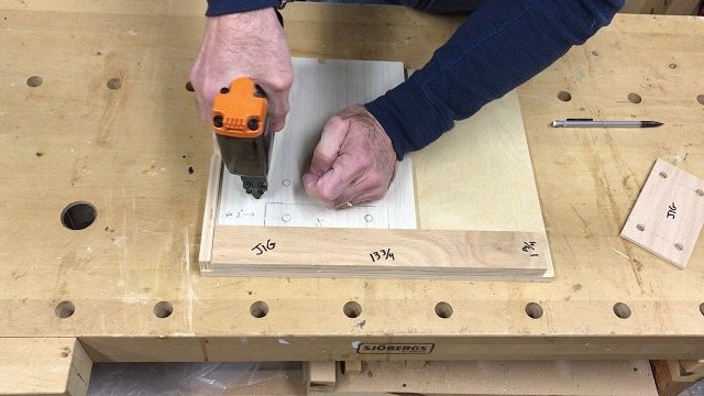
Step 3: Cut the slots
| 1 | | Cut the front and back slots from top and bottom.
I use a scroll saw, but a band saw or hand-held coping saw would work too.
|
Step 4 (Base Box Only): Marking and drilling the 3/8″ peg holes for the BASE BOX ONLY
| 1 | | Place the Front Edge Jig on the front edge of the box bottom |
| 2 | | Place edge scrap jigs along the left edge of the box bottom. |
| 3 | | Place the base sled (8-1/2″ across the box by 9″ long) in the front left corner against the jigs. |
| 4 | | Make sure the jigs align with the box bottom front and side and the base sled is in the resulting corner. |
| 5 | | Using 3/4″ pins, pin the sled in place with two pins, one in either corner.
 |
| 6 | | Place the 2″ Front Slot Jig on top of the base sled in the front left corner inside the 2 other jigs. |
| 7 | | Place the Drill Template Jig next to the Front Slot Jig. |
| 8 | | Draw circles in the holes of the Drill Template Jig. |
| 9 | | Take the box bottom and sled to the drill press and drill four 3/8″ holes where the circles are. |
| 10 | | Using a putty knife, pry off the sled. |
| 11 | | Using needle nose pliers, pull out the two pins. |
Step 4 (Radio Box Only): Marking and drilling the 3/8″ peg holes for the RADIO BOX ONLY
| 1 | | Place the Front-Edge-Jig on the front edge of the box bottom. |
| 2 | | Place edge-scrap-jigs along the left edge of the box bottom. |
| 3 | | Place the 2″ Front Slot Jig on top of the box bottom in the front left corner inside the 2 other jigs. |
| 4 | | Place one radio block piece (5-1/4″ x 3″) next to the Front Slot jig |
| 5 | | Make sure the edge jigs align with the box bottom front and side and the radio box is in the resulting corner.
 |
| 6 | | Using 3/4″ pins, pin the radio block in place with two pins, one in either corner. |
| 7 | | Place the Drill-Template-Jig on top of the radio block so it is flush on all edges. |
| 8 | | Draw circles in the holes of the Drill-Template-Jig.
|
| 9 | | Take the box bottom and radio block to the drill press and drill four 3/8″ holes where the circles are. |
| 10 | | Using a putty knife, pry off the radio block. |
| 11 | | Using needle nose pliers, pull out the two pins. |
| 12 | | Glue the 2nd radio-block on top of the one with holes in it. Be careful not to put glue where the holes are. Pin in place with 3/4″ pins. |
Step 5: Install the dowel pegs
| 1 | | Cut four 7/8″ pegs out of the 3/8″ dowel |
| 2 | | Glue them into the bottom of the base sled or radio block |
| 3 | | Clean off any excess glue with a rag |
| 4 | | Allow to dry |
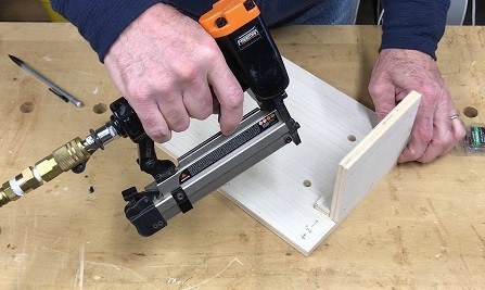
Step 6: Main Box assembly (all pins are 23 gauge 3/4″)
Prep: Dry fit all the pieces together to make sure all fits correctly.
Prep: Make sure the Front Edge Jig is flush with the front edge of the bottom and the right side is flush with the right edge of the bottom.
| 1 | Glue and pin the floor brace to the bottom. | 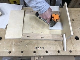 |
| 2 | Glue and pin the front right panel brace into the inside right side. | 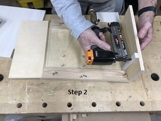 |
| 3 | Glue and pin the center support (5-1/4″ x 6-3/4″) on the left side. | 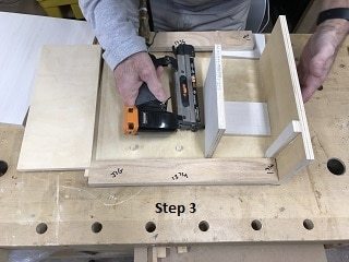 |
| 4 | Glue and pin the box right side bottom edge. | 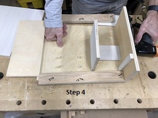 |
| 5 | Glue and pin the ceiling brace on both left and right. | 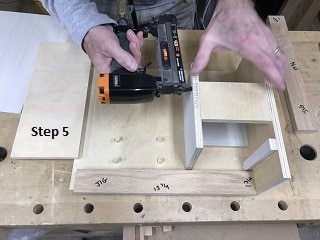 |
| 6 | Pin the box right side in from the bottom. | 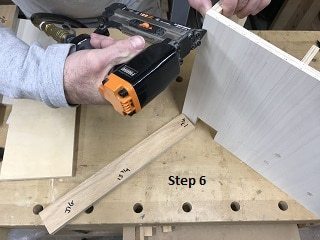 |
| 7 | Glue and pin the box left side bottom edge. | 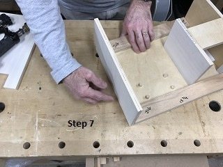 |
| 8 | Glue the top on and pin it on both top edges. | 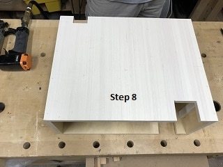 |
| 9 | Press down on the center support and pin above the ceiling support. | |
| 10 | Measure 5-1/2″ from the right side on both top and bottom of the box. This marks the location of the center support. Pin into the center support. | |
Step 7: Measuring for the top panel and footpads
| 1 | | Measure the box top left to right and mark the center at 7-3/8″.
Measure the other direction to confirm. |
| 2 | | Measure the box top front to back and mark the center at 5-7/8″.
Measure the other direction to confirm. |
| 3 | | Perform steps 1 and 2 for the box bottom. |
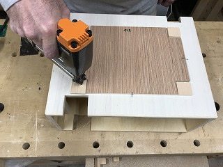
Step 8: Round the outer edges
| 1 | | Use the handheld router with 1/4″ rounding overbit to round all outer edges |
| 2 | | Exclude the inside of the slots |
| 3 | | I use bench biscuits to keep the box from sliding |
Step 9: Attaching the top panel and footpads (Using 1/2″ pin nails)
| 1 | | Put the Top Panel Jig on top of the top panel. |
| 2 | | Trace the jig cutouts onto the top panel. |
| 3 | | Cut out the top panel cutouts by cutting inside the pencil marks. |
| 4 | | Place the top panel on top of the Top Panel Jig and transfer the front and side center edge marks.
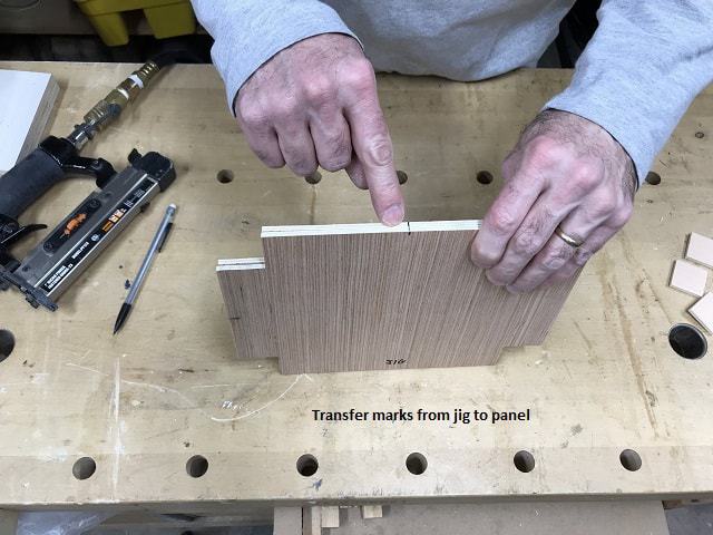 |
| 5 | | Place the top panel on the box top and align the center marks on both panel and top. |
| 6 | | Use the 2″ Top Panel Sizer Jigs to make sure the top panel is centered. |
| 7 | | Pin the top panel to the top (without glue) |
| 8 | | Turn the box over |
| 9 | | Place the Top Panel Jig on the bottom and align with the centering marks on front and sides |
| 10 | | Use the 2″ Top Panel Sizer Jigs to make sure the Top Panel Jig is centered. |
| 11 | | Place each 1-1/4″ square footpad about 1/16″ away from the inside cutouts of the jig.
Pin in place with no glue.
 |
| 12 | | Trim the 4 footpad-sized pieces cut out in step 3 above so each is 1-1/4″ square or less. |
| 13 | | Pin these 4 footpads at each of the box bottom corners. No glue needed. |
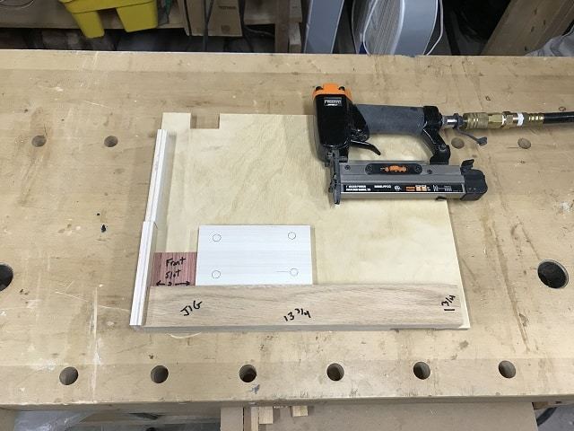
Step 10: Attach the board panel (R-Pi or TNC-Pi) (Using 1/2″ pin nails)
| 1 | | Turn the box on it’s back |
| 2 | | Place the board Panel Sizer jig (7/8″ tall) on the top edge of the panel area. |
| 3 | | Place the circuit board panel below the jig. |
| 4 | | Pin the panel in place
 |
| 5 | | Place the Board Panel Hole jig over the board. Drill the holes through the template into the panel. |
Step 11 (Base box only) Attach the O-scope panel (Using 3/4″ pin nails)
| 1 | | Place the o-scope panel hole jig on top of the o-scope panel |
| 2 | | Drill throught the template holes into the panel. |
| 3 | | Align the oscilloscope panel along the front edge of the base-sled,
put 2″ inches away from the left edge.
Use the Front Slot Jig to set the correct distance.
This 2" space allows the HP DPS1200FB to fit so the supply's fan can exhaust to the front. |
| 4 | | Place the o-scope panel support (5-1/4″ x 3/4″) behind the panel. |
| 5 | | Glue and pin the panel support |
| 6 | | Glue and pin the o-scope panel from front and bottom
 |
Step 12: Sanding
| 1 | | Use a palm sander on all edges. |
| 2 | | Hand-sand to smooth any rough or sharp edges. |
Final result (prototype)


