NinoTNC and Kenwood TK Mobiles RJ12
This page describes creating a cable to connect the speaker jack and microphone jack of a Kenwood TK radio to a NinoTNC, TNC-PI or Kantronics KPC-3.
This cable uses a 6pin microphone connector and is compatible with the
TK705, TK805, TK808d,
TK705d, TK805d (note: See
article on an optional improvement to the TK705d/TK805d here)
TK730, TK830 (except that the earphone/speaker plug is replaced with wiring to the Kenwood molex connector)
TK740, TK840, TK840(N)
TK760, TK762, TK760G, TK762G, TK763G, TK860, TK862, TK860G, TK862G, TK863G (and high power H varients)
TK780, TK880.
Even though many of these radios have 8 pin mike jacks, the 6 pin varient is perfectly suitable.
During assembly, I suggest crimping the wires to the RJ12 first, then apply heat-shrink tubing to the RJ12 end of the wire, then solder the DE9, and finally solder the 3.5mm speaker plug.
These instructions create a cable idealized for the MOD-box stack.
The measurements used are 12" from the RJ12 to the speaker-plug, and 9" from RJ12 to DE9.
Parts and tools required:
- DE9 solder-pin male connector parts-express 090-550
- DE9 shell parts-express 090-695
- 3.5mm (also called 1/8") mono audio plug parts-express 092-158
- 2" piece of 1/4" heat shrink tube parts-express 080-624
- RJ12 crimp-on 6-pin connector
- 28" piece of CAT5 or CAT6 wire
- two 4.7k resistors, yellow purple red, preferably 1/8th watt (so they fit easily)
- soldering iron, solder
- RJ12 crimping tool
I have had very good luck with DE9 connectors and audio plugs from
Parts Express.
I recommend:
090-550 parts-express 9 Pin Male Solder Type D-Sub at 45 cents each
090-695 parts-express 9 Pin D-Sub Hood at 58 cents each
092-158 Neutrik Rean NYS226L 3.5mm Mono Plug Nickel 0.25" Entry at 73 cents each.
Try to find real copper CAT5 or CAT6 wire.
There are 3 critical signals, plus ground, connected to the TNC.
Those signals connect to the TNC on these pins of the DE-9 connector.
This drawing is of the solder cups on the back of the radio-cable DE9 from the perspective of the inside of the D-sub Shell.
I have arbitrarily selected color coding for the signals using colors available on typical CAT5 wire.
I chose CAT5 wire because it is easy to crimp into an inexpensive RJ12 connector.
The color codes are shown for the wires which are connected directly from the DE9 to the CAT5.
Pin 1, TxData, is fed through a 4.7k resistor and then into the Blue wire.
Click on the images to enlarge
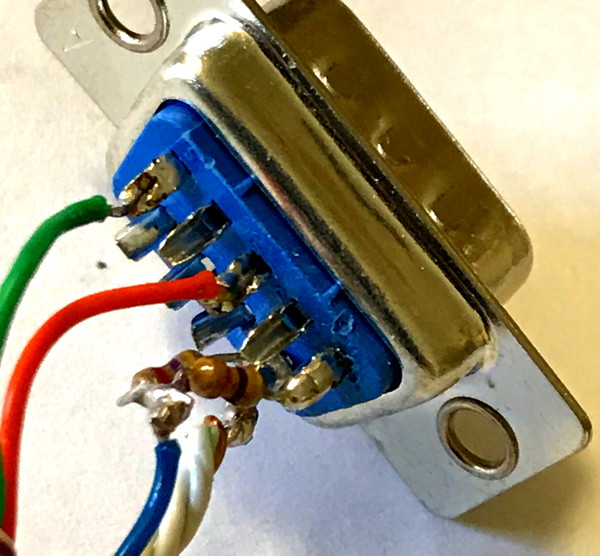
The pair of resistors allow for a much less stiff adjustment on the TNC.
If pin 1 was connected to the mike/txaudio wire directly, the TXLEVEL pot becomes very sensitive.
If using the TNC-PI, R7 is so sensitive that it is almost impossible to find the proper level to saturate the radio passband, without overdriving.
With the addition of the two resistors in the DE9 connector, it is really easy to set R7.
Assembly
RJ12 Connector
Please note that the RJ12 connector may be used even on Kenwood TK radios which have an 8-pin microphone connector.
The remaining unserviced 2 pins are not used in our application or are redundant with the rear-panel 3.5mm connector.
Also note that the standard Ethernet color codes were not followed and we're crimping the BROWN and BROWN/WHITE wires
into the connector but not connecting them at the DE-9 end of the wire.
- Strip one end of the CAT5 wire such that there is about 16" of insulated CAT5 on one end, and then 12" of bare twisted wires.
- Dispose of excess.
- Now trim back the orange, brown and blue pair to 3/4".
- Fold the green wire back over the insulation.
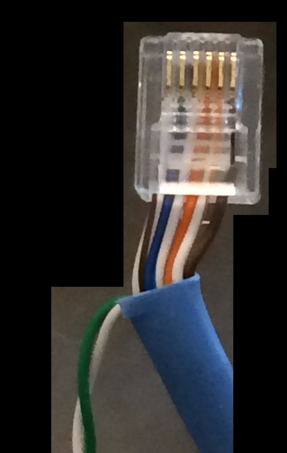
- Crimp six wires into the RJ12 connector as shown, leaving the GREEN and GREEN/WHITE pair folded away from the connector.
We’re connecting to 6 pins on the radio though only the middle 4 are important.
Based on the image of the RJ12 just below, this is the order from left to right.
HOOK — BROWN/WHITE - don’t care
MIC — BLUE
ME — BLUE-WHITE — External Microphone Ground
PTT — ORANGE
GND — ORANGE/WHITE — PTT Ground
PSB — BROWN - don’t care
Note! These wiring colors are not anybody's standard.
Please crimp with these colors.
The two wires on the ends, white/brown and brown, are not important except that they make it easy to place the other four wires in the connector.
The colors are:
- white/brown
- blue
- white/blue
- orange
- white/orange
- brown
Put heat shrink over the cable over where the green wire folds back and all the way up to the connector.
I found that a 2" piece of heat shrink was adequate.
DE9 Connector
Strip the DE9 end of the cable back about 3/4".
- Unwind the pairs so you have 8 separate wires.
- Cut the BROWN wire back to strip point.
- Cut the BROWN/WHITE wire back to about 1/4" from the strip point.
We're not soldering those and they contain signals we do NOT want shorted.
- Strip the insulation back 1/8" on the solid blue, solid green and solid orange wire.
- Strip the insulation back 3/8" on all of the white/color wires.
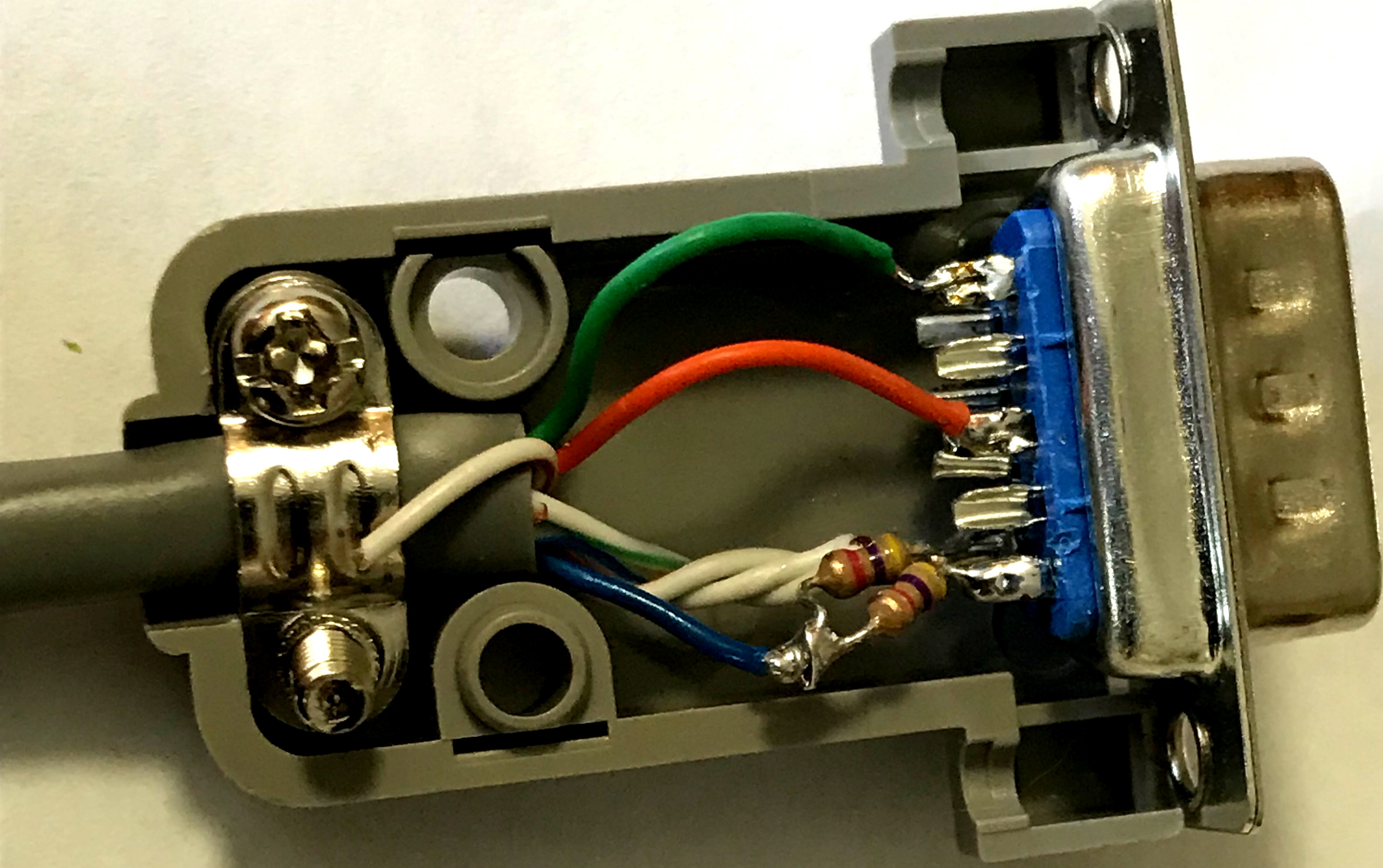
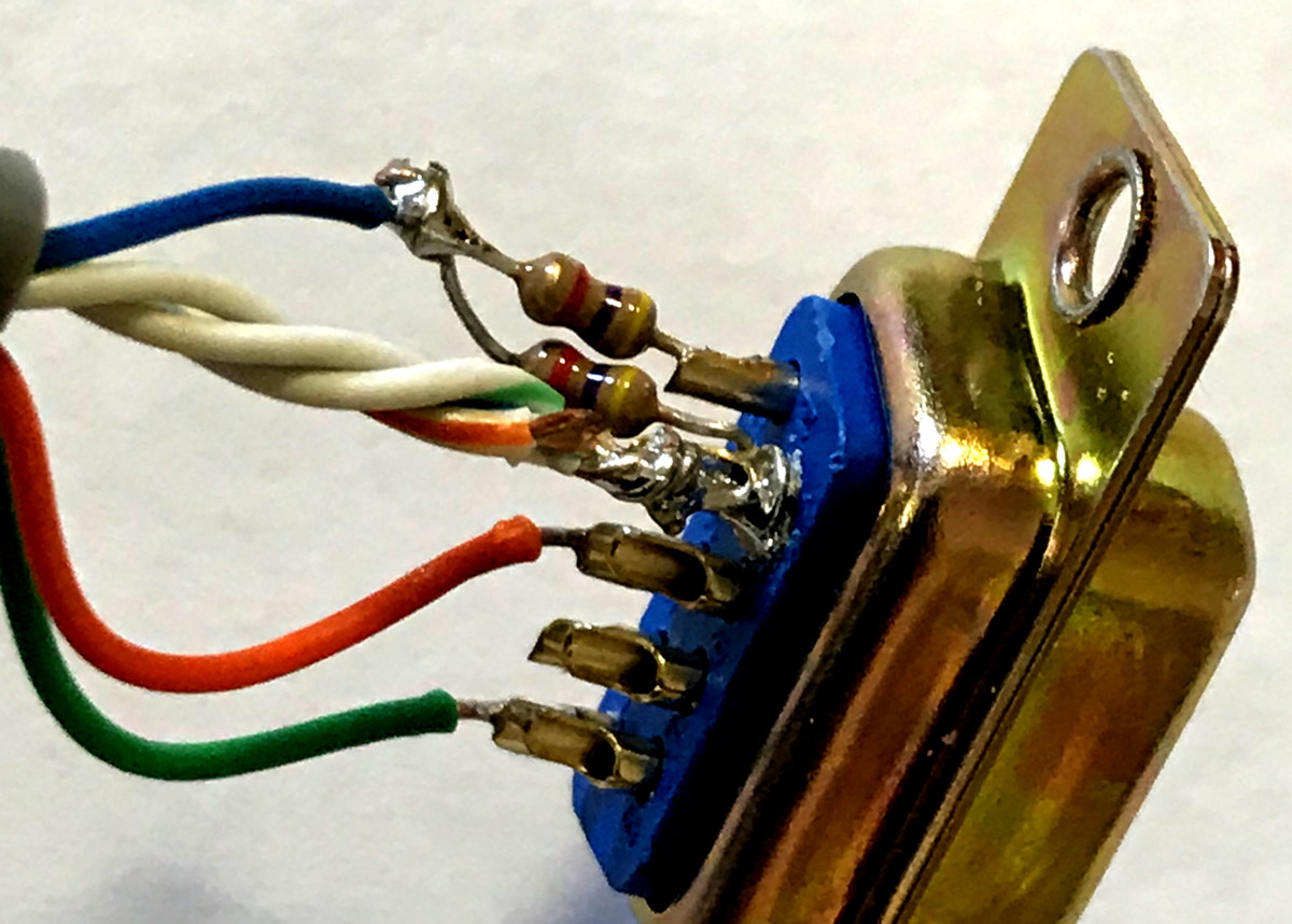
- Twist the stripped parts of the ground wires, GREEN/WHITE and BLUE/WHITE and ORANGE/WHITE, together.
- Trim, and solder the bundle of 3 wires to pin 6.
- Solder the Green wire to the DE9 connector pin 5 as shown at the top of this page.
- Solder the Orange wire to the DE9 connector pin 3 as shown at the top of this page.
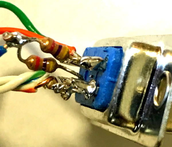
- Twist one other end of both resistors together
- Apply solder to the twisted pair for the first 1/4" near the resistors.
- Cut the twisted bundle to about 1/4".
- Take your two resistors and cut one end of each resistor to about 1/4".
- Solder the two individual ends of the resistors 1-each to pin 6 ground and pin 1 TxData (pin 6 already has the twisted grounds bundle so be careful).
- Solder the blue wire to the twisted pair end of the resistors. (The blue wire feeds the transmit audio to the TK radio)
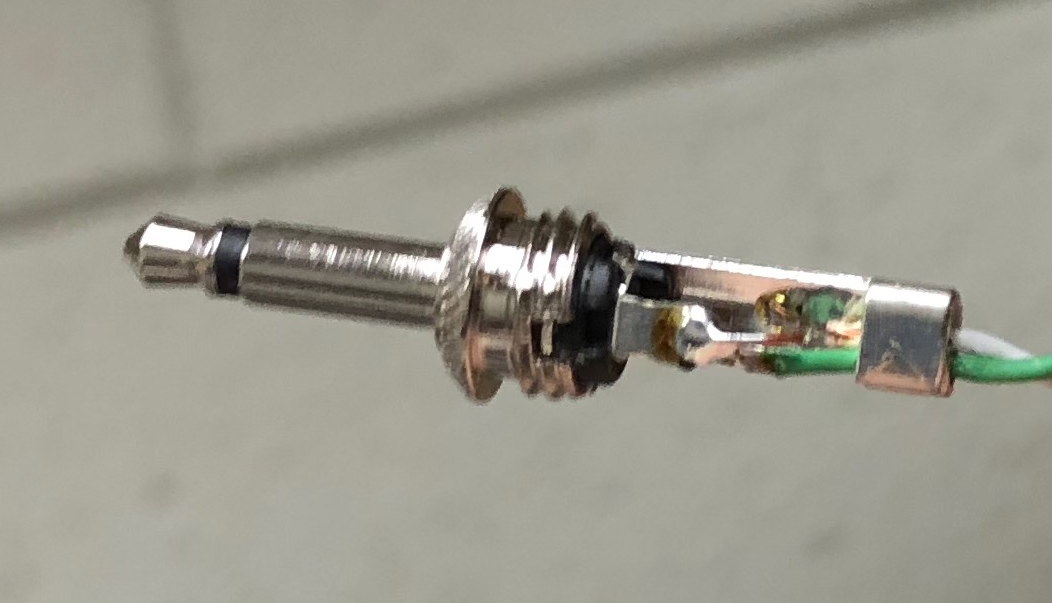
Earphone plug
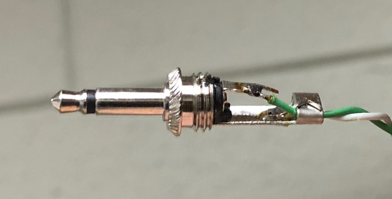
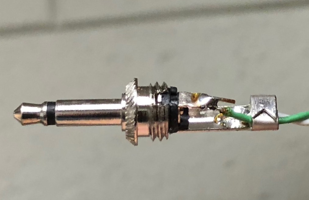
Solder 12" long green wire to center conductor of earphone plug.
Solder white&green wire to ground of earphone plug.
Note that reversing these two wires on the earphone jack is the number one cause for failure of this cable!
Where applicable, make sure you put the plastic insulator, spring, and screw-on cover over the wire, in the proper order and orientation, before soldering!
For more information, consult
TNC and Radio Adjust and Test or the operations guide for your TNC.