|
The work detailed on this page requires a steady hand and an attention to detail.
By opening the radio, you are assuming responsibility for the work or failures of the work.
This guide is provided for information only, and the authors assume no responsibility for damage to personal property or side effects.
Do not attempt to perform this procedure if you are unwilling to risk your radio!
Please be careful.
|
Yaesu FTM-3100r wiring for 9600 baud
This procedure is new as of April 2, 2023.
Modified August 21, 2023.
I added notes about NinoTNC adjustments at the bottom of this article June 27, 2023.
I re-shot some of the images to correct the wire-wrap colors so they more or less match the CAT5 wires, August 21, 2023.
Please send success/failure/problem/correction/hints to
[email protected].
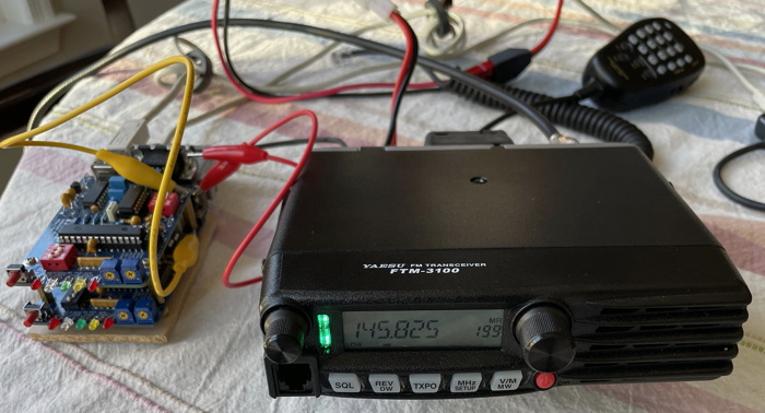
The FTM-3100R is an analog 2-meter FM transceiver that can have a TNC data-connector added, enabling the radio to participate in sending and receiving 9600-baud FSK packet signals.
At the time of writing, this radio is widely available for about $150 retail.
The only complaint anybody has had about this radio is that the fan runs all the time?
We're still gathering data/hacks and input on that.
It appears that the fan is off when the radio is first turned on at room temperature.
If one transmits for just a few seconds, the fan comes on.
It will go back off after a bunch more seconds.
Eventually the radio heats up just from having the receiver turned on.
At this point the fan never turns off again.
I verified this with a new radio that had never been used or modded.
The FTM-3100R shares its main board with its C4FM-capable sibling, the FTM-3200R.
Because of this, there are convenient circuit traces on the main board that carry discriminator audio to the (unpopulated) DSP daughter card, and feed wideband audio to the two-point FM modulator circuit.
A straight-forward procedure can add a dedicated packet radio port, while keeping all normal features of the radio completely functional.
The FTM-3207R UHF version of the C4FM radio is also convertable using these instructions -- alas, that model is discontinued.
The FTM-3100R is quite a boon to our project as it scores above our other prime 9600 candidate, the Tait TM8105, in several ways.
The FTM-3100R is more powerful, 65 W, has an S-meter, easy frequency selection, monitor speaker with volume control (does not affect Rx packet data).
The squelch affects the monitor speaker without muting the receive data.
It is unclear if the FTM-3100R is better at 9600 baud, but it works well with 4800 baud.
The FTM-3100R was discontinued in late 2024, alas.
It was replaced by a more expensive unit which is the FT3165Rasp.
—— Procedure demonstrated by Nino KK4HEJ and reworked by N2IRZ and KA2DEW.
Test the radio for proper power, reception, front panel illumination, fan operation, button and knob behavior, before this procedure.
This procedure will
definitely violate the warranty.
Ensure your radio is disconnected from all external power, accessories, and antennas.
Prepare a large, flat, clean workspace.
Use adequate lighting and eye protection.
Tools required:
- Medium phillips head screwdriver
- Fine flush-cut side cutters
- Long nose plier
- plier
- Wire stripper for CAT5
- Wire stripper for 30gauge wirewrap wire
- Drill and 1/4 inch drill bit
- Temperature controlled soldering iron with 0.016" tip.
Some tip cleaner
- Heat gun for heat-shrink tubes
- Smart phone or other magnifing apparatus
Supplies required:
- 2 feet of CAT5 wire or equivalent
- DE-9 male connector and shell
- 4-6 stud ring-terminal, I used: Gardner-Bender 22-18-AWG 4-6-Stud Ring-Terminal Vinyl Red 10-Pack 15-101
- a few inches of 1/16" heat shrink or some equivalent
- Fine rosin-core solder
- Two small nylon wire tie -- 1/10th inch wide or so.
The exact unit is not important.
- 30 gauge solid wirewrap wire, hopefully in 3 different colors, and ideally in red, blue and green.
Remove Top Shell
Note the two black tabs that go off the back of the top shell, one over the power cord, and one over the fan.
These tabs make it easy to identify the back vs the front of the top shell.
Remove three phillips head screws retaining the top black plastic shell of the radio.
There is one screw on the top, and one on the left and right side of the radio.

The plastic top cover of the radio is snap-fit in place over the aluminum mounting boss protrusions on each side.
Use your fingers to pry the cover over one side of the protrusions and then the other.
Study the PCB and identify the solder points
Study the following several pictures to identify the signal connection points.
There are three 30-gauge wires to attach.
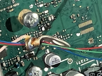
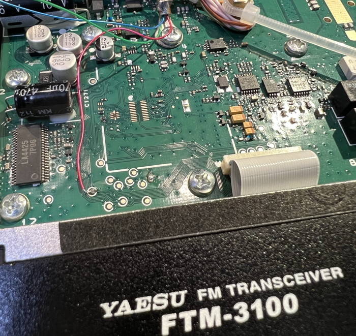
This photo is looking down on the top side of the radio, having removed the cover.
Notice the brass spacer to which the center of the top cover would be screwed.
Also, in the front left of the PCB, notice the set of pads for an integrated circuit which is unpopulated -- These are pads for a surface mount "mezzanine" connector used by the C4FM daughter card in the FTM-3200R model.
These two locations, the region around the unused pads, and the region around the brass spacer, are important to the modification, as you'll see in following images.
click to embiggen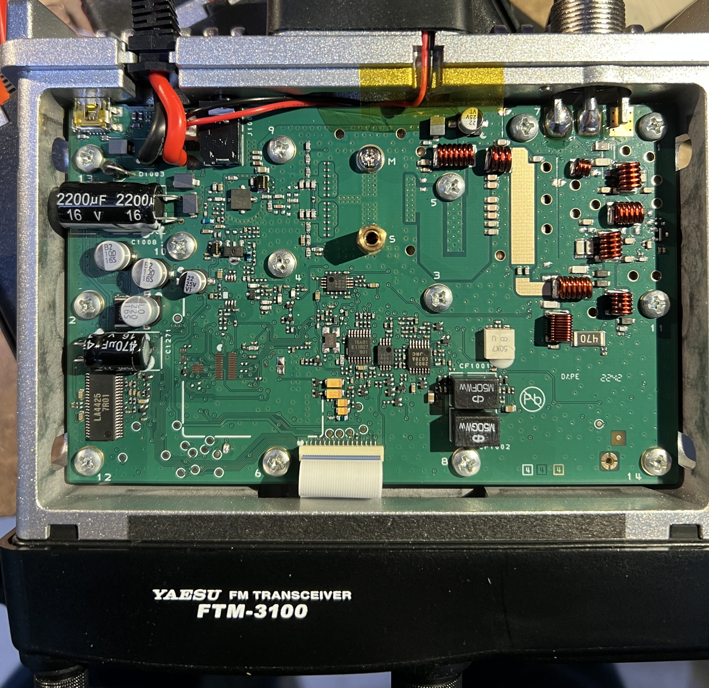
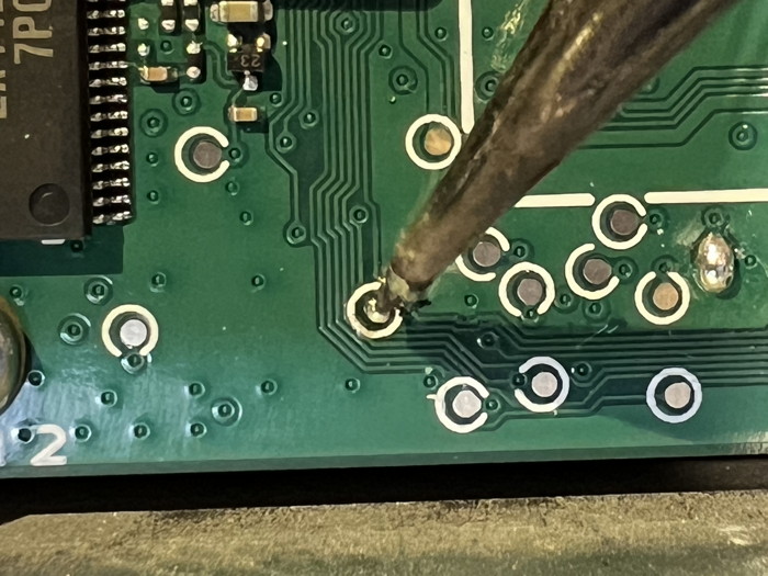
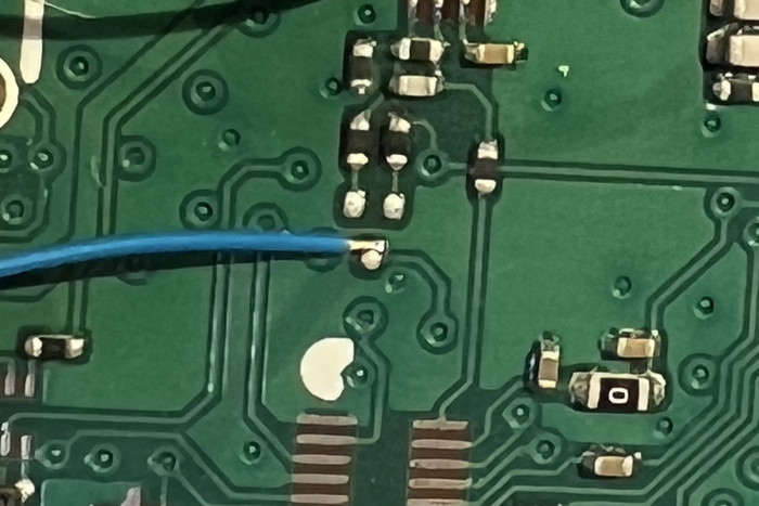
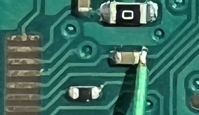
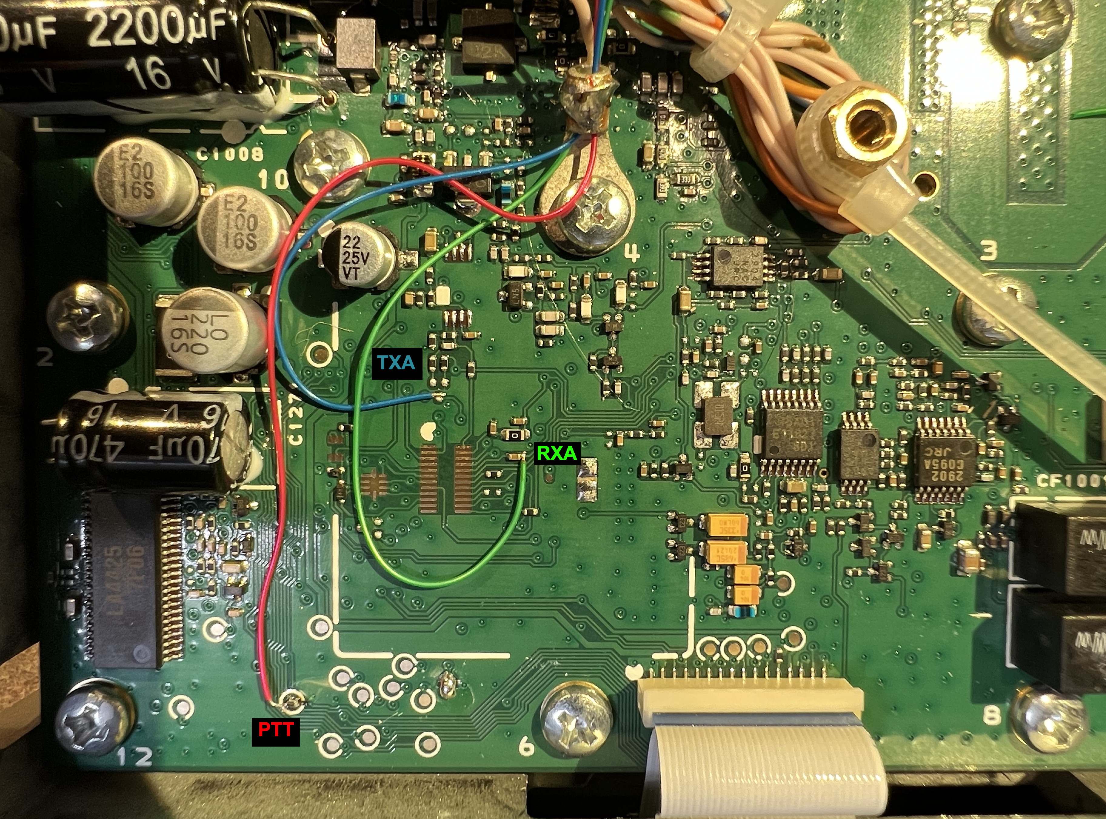
This annotated image shows attach points for PTT, TxAudio, RxAudio.
The TXA and RXA spots are pre-tinned.
The PTT spot needs to be tinned.
click to embiggen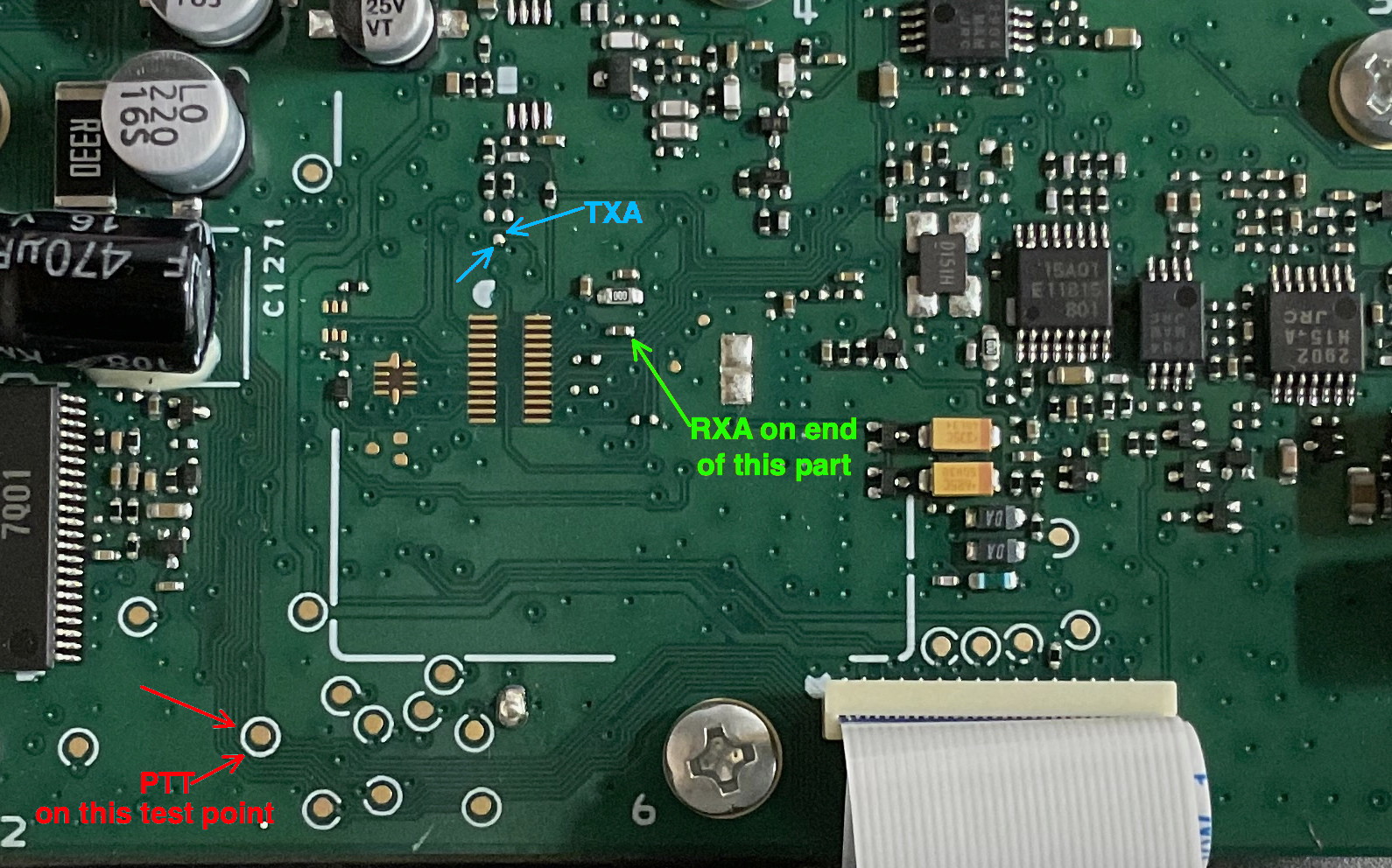
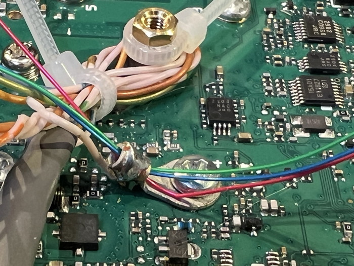
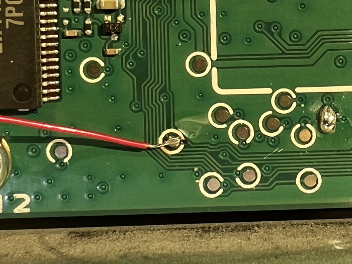
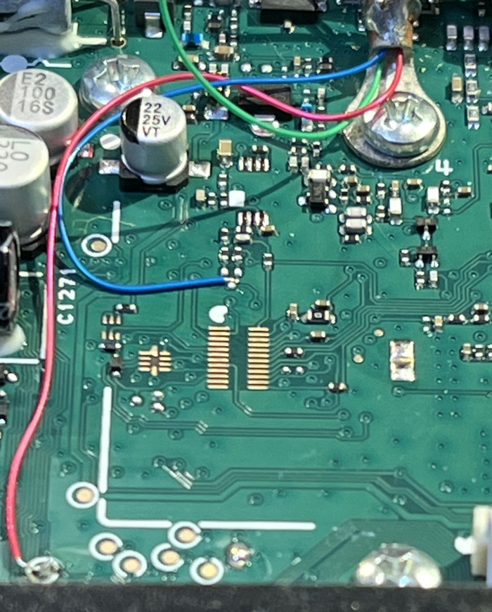
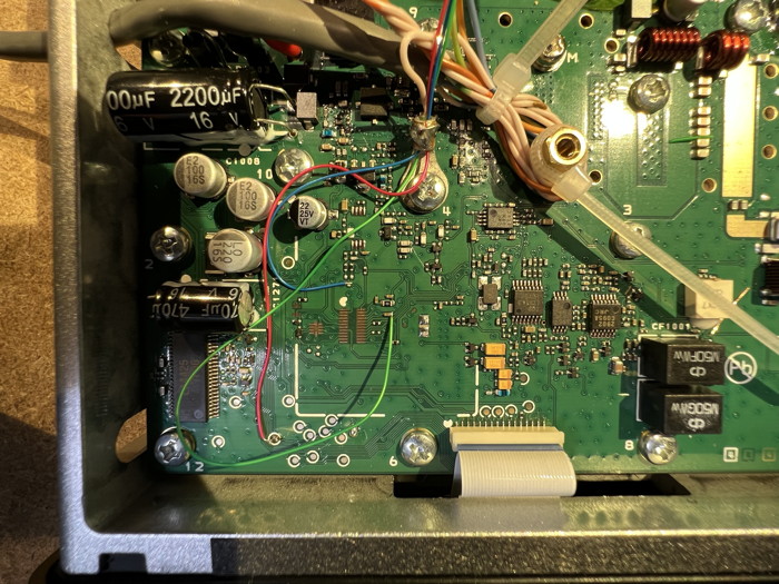
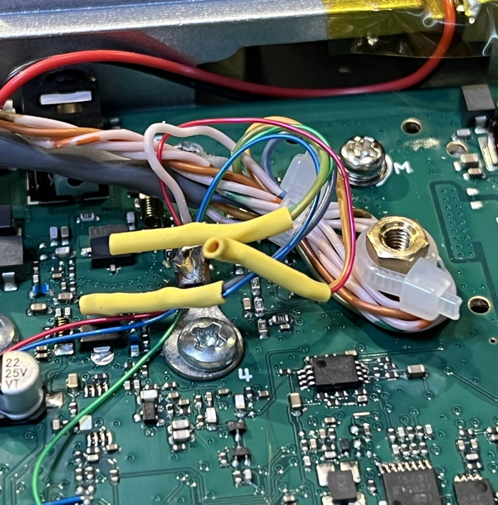
This photo shows the wires attached, black to PTT, red to TxAudio, blue to RxAudio.
Note that my choices of color were not ideal.
I'll try to do this mod over again at some point with idealized colors.
PTT is connected to the bare test point in the buss circuits in the lower left part of the picture.
TXA is connected to a pre-tinned pad.
RXA is connected to one side of a existing surface mount capacitor.
click to embiggen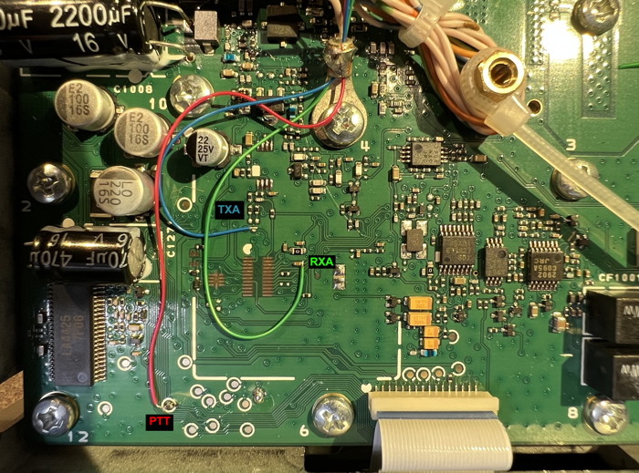
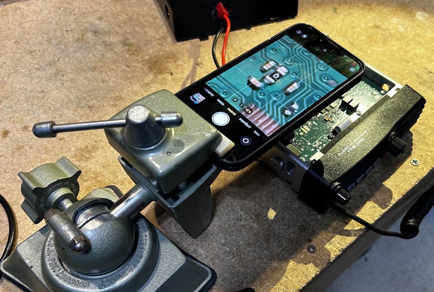
Set up a magnifier so you can see your solder points.
I use a smartphone.
Warning, wrecking your $800 smart-phone to hack on a $150 radio will not be easy to explain to the budget committee.
Verify Task Sanity
Make sure you are ready to do this.
|
I recommend setting up your magnifier as described above and then manipulate a cold soldering iron to demonstrate to yourself that you are steady and able to see the points in question while holding the iron and the wire.
|
- Unroll some wirewrap wire and test your wire stripping tool.
Notice how much force it takes to strip the wire.
This will be important later.
Drill hole for cable
In the next step, you will drill a 1/4 inch hole into the side of the black cover about 1/2 of an inch forward of the back left side of the shell and about 1/2 of an inch down from the top edge.
You'll do this with the cover removed.
Make sure you don't drill into your workbench.
That's embarassing.
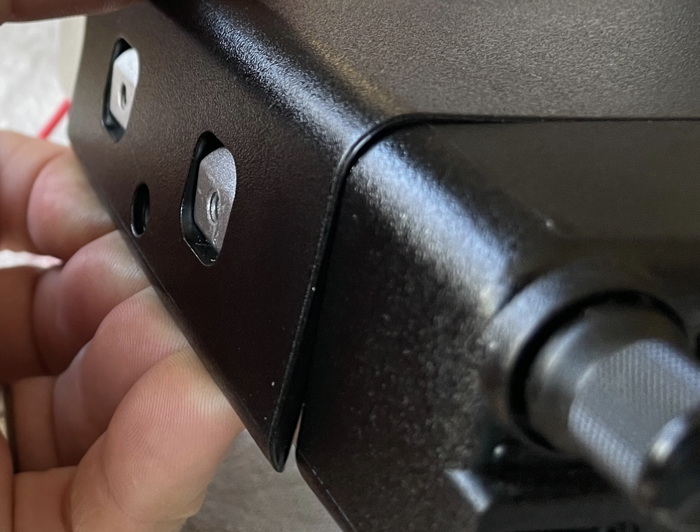
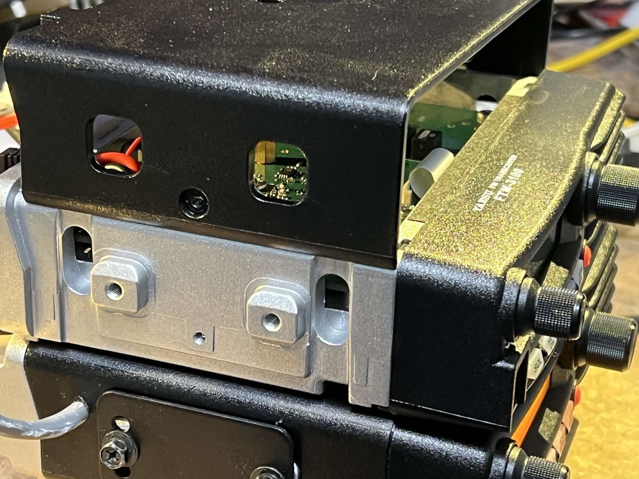
The hole in the black cover is going to line up with a pre-existing hole in the cast-aluminum chassis.
The hole is going to be behind the left rear mounting bracket screw.
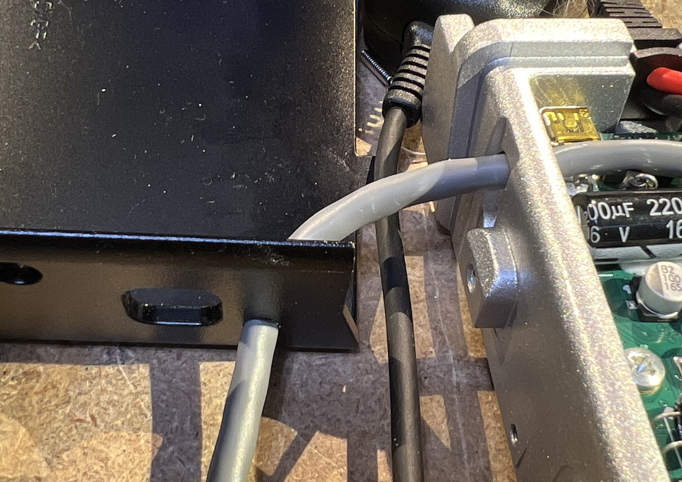
This photo is of a new unmodified cover sitting on top of the radio chassis, sitting on top of a re-assembled, modified, radio.
click to embiggen
Test penetration of the CAT5 wire into the chassis.
If your cable doesn't fit, pick the next larger drill bit and enlarge the hole.
Put the top cover and CAT5 wire asside until a later step.
Wiring inside the box
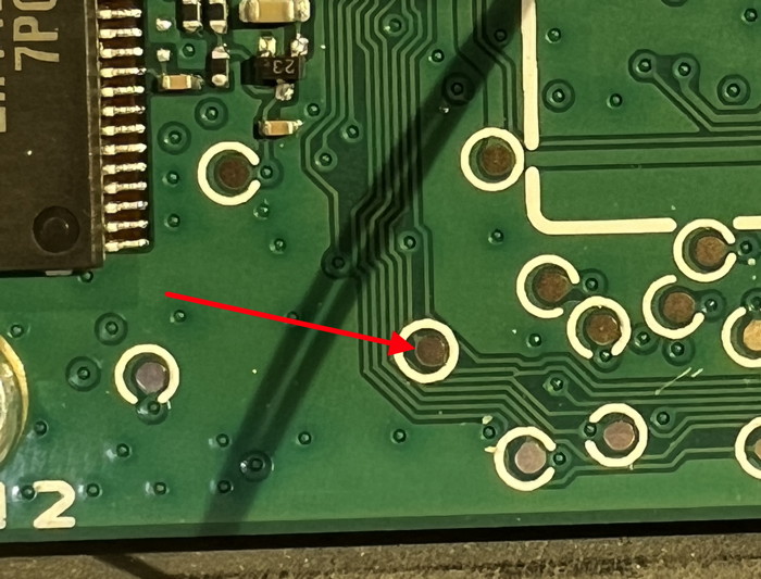
- Unscrew the PCB hold-down phillips head screw that is to the left and slightly to the front of the brass spacer (circled in this photo).
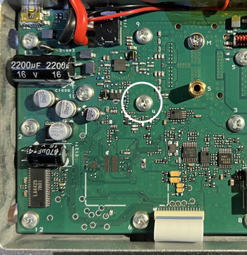
- Make sure your ring-terminal fits under that screw and doesn't overlap any of the surface mount parts.
We will be bending the wire-attachment part of the ring terminal up a little so that part doesn't need to clear the surface mount parts.
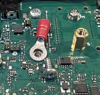
- Restore the screw to its hole (without the ring terminal) but do not tighten it.
- The CAT5 wire should be stuffed from the outside of the black cover such that about 12 inches of the wire is inside the cover.
You'll be pulling some of that back out while attaching the ring terminal after one of the wires is soldered to it.
Route the wire through the chassis in the left side (toward the rear) hole Yaesu cleverly provided us.
- Strip 4 inches of the jacket off the CAT5 wire.
- Cut the extra insulation and string.
- Unwind the orange, blue and green twisted pairs.
Wind the orange-striped, green-striped wires together with the brown and brown-striped wires.
- Strip the blue-striped wire to give us 1/2" of bare wire at the end.
Do the same with the solid green, solid blue and solid orange wires.
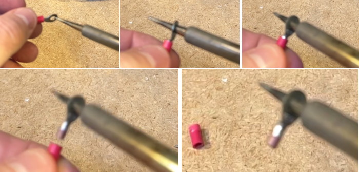
- Obtain your ring-terminal.
- Remove and discard the insulating jacket (if any) around the cylinder part of the ring-terminal
- Remove insulation from the ring terminal's crimp end.
I use a soldering iron to heat up the ring terminal so the insulation pulls right off.
Don't burn yourself and instead dump the clean lug onto your soldering iron sponge.
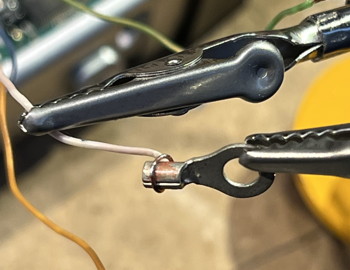
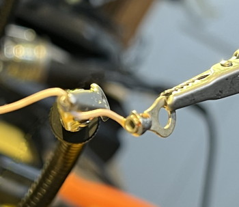
- Using a tool, hold the ring-terminal by the ring-end and solder the blue/white striped wire to the outside of the top of the crimp-end of the terminal.
A Helping Hands rig is fabulously valuable for this piece.
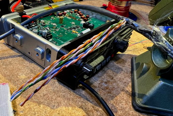
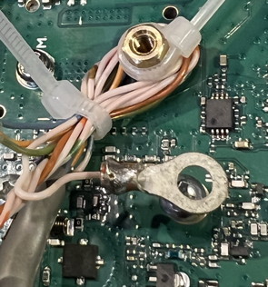
- Push the CAT5 out of the radio from the inside and route the CAT5 wire across the back of the radio, turning about 45 degrees toward the brass spacer, and then wrap all of the exposed CAT5 wires around the spacer.
There will be about 1" of exposed wire in between the remaining CAT5 jacket and the spacer, and then a couple of inches of twisted and separate insulated wires going around the spacer.
Tie-wrap the wires together to make a package that won't pull out of the radio.
Leave enough room to screw down the ring terminal. See the images.
Apply the 2nd tie wrap to the top of the spacer to keep the insulated wires from pulling off (while the box top is off).
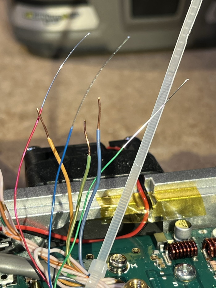
- Unroll a foot or so of all 3 of the wire-wrap wires, or cut lengths of 12" or so of the 3 wires.
- Twist the last inch of the three wirewrap wires together
- Push the twisted end of the wires through the crimp-cylinder end of the ring terminal so the wires come out the ring end of the ring-terminal.
- Push about 6 inches through the crimp-cylinder toward the front panel of the radio.
- Using a plier, bend the ring up from the crimp-cylinder so the crimp-cylinder is about 30 degrees up from the PCB when it is screwed down.
Be careful not to damage or kick the wirewrap wires during this.
- Being careful not to damage the wirewrap wires, screw the ring terminal down using the sheet-metal-screw you left inserted in a previous step.
- Cut the twisted portion off the ends of the bundled 3 wirewrap wires.
- Place the warranty card across the front of the PCB and partially covering the front panel to protect the radio from loose tools and dripped solder.
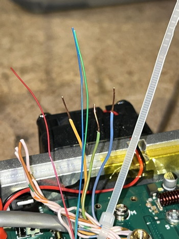
- Using your 30-gauge wire stripper, strip 1/4" off of each of the 3 wirewrap wires.
- Tin the ends of all 3 of the wirewrap wires.
It's ok to make the solder rather thick.
- Cut the wirewrap wires back to 1/8" of stripped and tinned end.
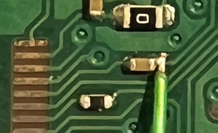
- Identify which wire will go to the PTT pad using this photo.
In my example, you'll be using the red wirewrap wire on the PTT pad.
- Set up your magnifier and identify the PTT solder point.
- Apply solder to the PTT solder point.
- Take the ends of your wirewrap wire, and identify which wire goes to the PTT pad. (red, in my case)
- Route the wire so it comes toward the solder-point from the left side of the radio (as seen in the above image).
- Lay the tip of the wire across the point and touch it with the soldering iron tip.
- After removing and securing the soldering iron, tug on the red wire and make sure it doesn't pop off (using your skillz to know how much to tug!)
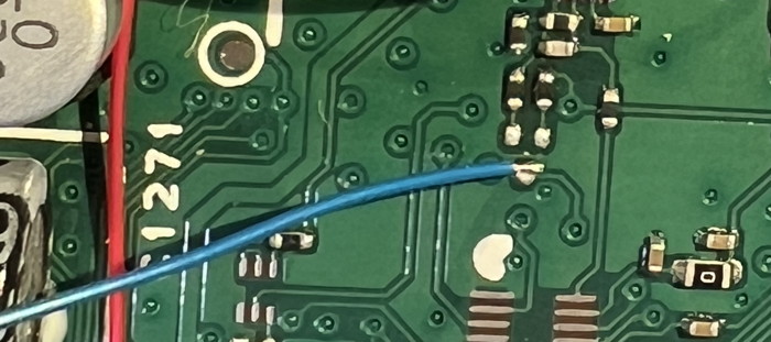
- Route the wire up the PCB toward the lug and remove some of its slack.
The wire should lay to the right of the big capacitor C1271 so that it avoids the other two solder points.
- Now take the TXA wirewrap wire and route it to the TXA point from the left.
- The TXA point is pre-tinned so you can lay the wire end across the solder point and tack it down.
- Umm.
1/8 inch is way too long here.
Try 1/32 inch.
- That's better.
- Put the iron on it.
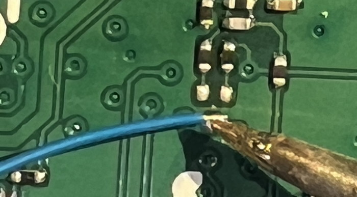
- Done.
Make sure it can stand some calibrated tugging.
- Route the TXA wire around to the left and take up slack at the ring terminal.
Put a finger on the TXA connection point while you move the wire with the other hand.
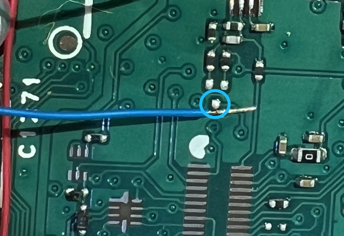
- Route the green wire around to the left and come to the indicated capacitor from the front of the radio (down in this image).
Touch the RXA wire to the edge of the indicated capacitor as shown in this close-up.
Verify that the length of the uninsulated part of the wire is rational as per this image.
- RXA wire is soldered.
Make sure it is can stand some calibrated tugging.
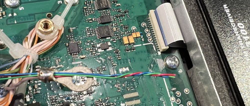
- Zoom out and look at all three wirewrap wires, soldered as they need to be.
- Route the green wirewrap wire and take up slack at the ring terminal.
- Cut the extra wirewrap wire.
In this image I show just adaquate amount of extra wire for wire-wrapping.
Beware that the wire stripper may require a significant amount of force to hold the wire from ripping through the ring terminal.
You might want to leave an extra inch just to make sure you can get your hands on the wire when stripping it.
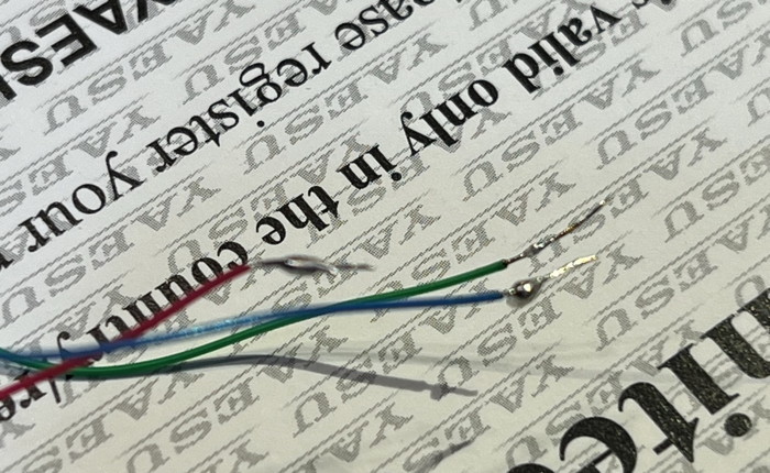
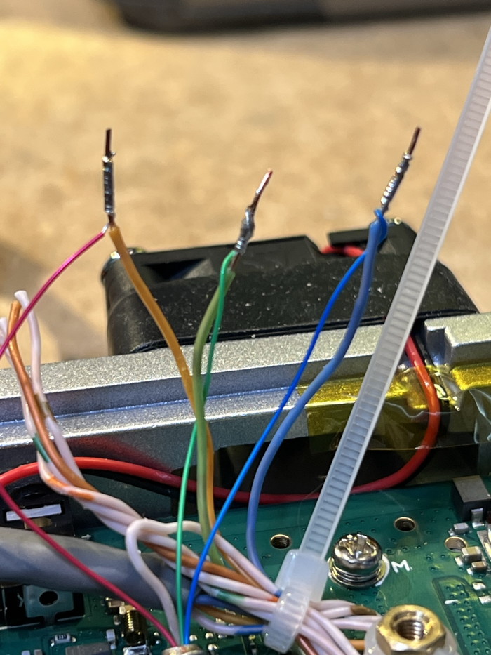
- This image shows the wires stripped appropriately.
- Wrap the wires using a wirewrap tool if you have one.
By hand otherwise. Then solder the wires.
- Heat shrink the connections.
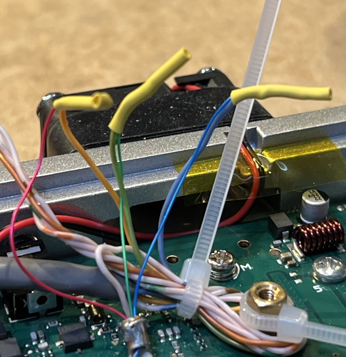
- Cut the excess length of the tie wraps and lay the heatshrunk wires appropriately for case closure.
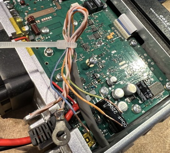
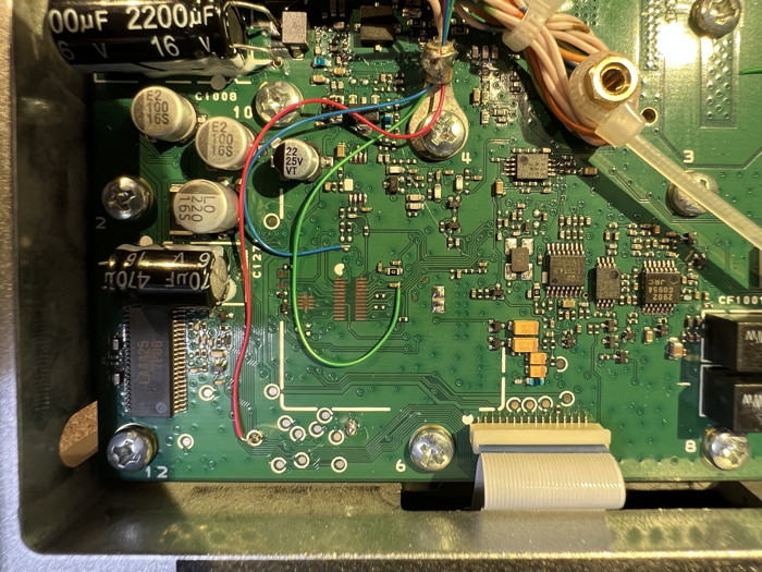
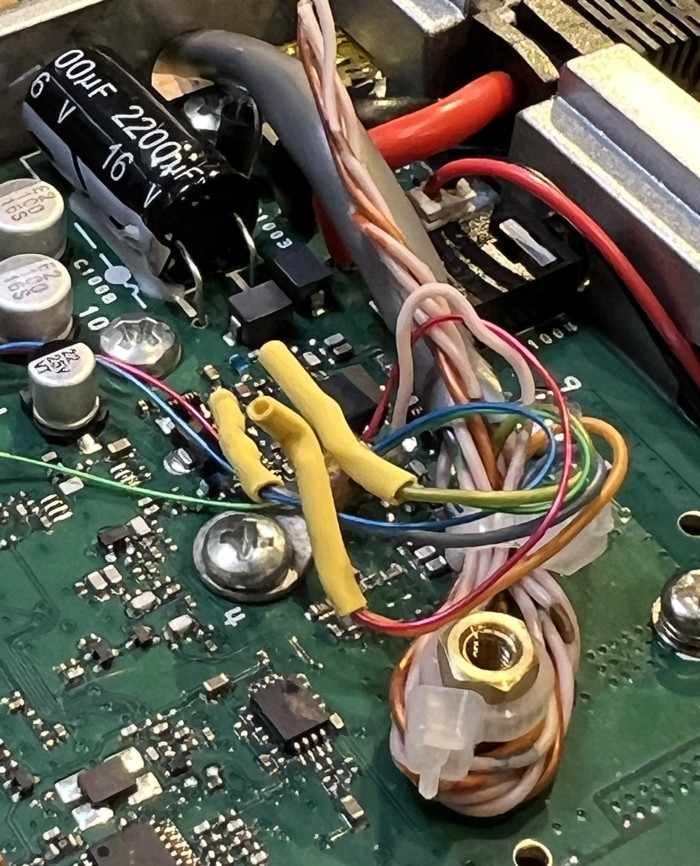
- Here is another view of the innards before closing the case.
DE-9 connector and cable
While pulling on the CAT5 wire gently from outside the black cover, place the cover on top of the radio and snap it into place.
Put the three screws in place to attach the black cover to the chassis.
Cut the CAT5 to length so it reaches the TNC.
Strip the ends as appropriate for a DE9 connector.
Remove the solid brown and brown striped wires.
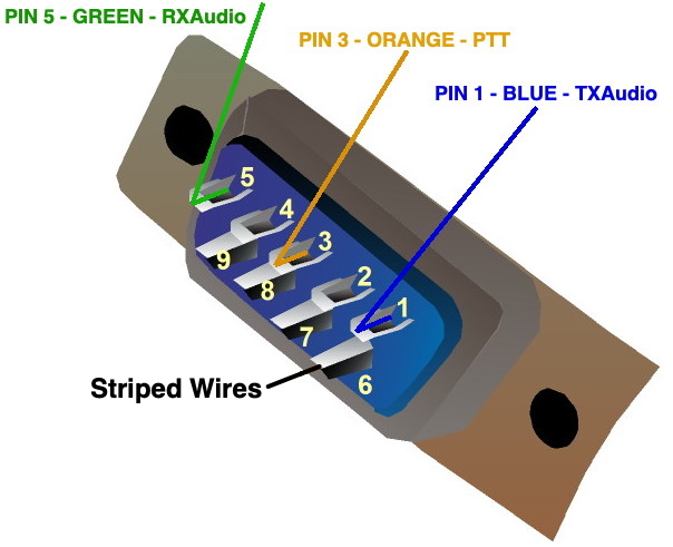
Solder the solid orange, solid blue, solid green and blue striped wires onto the DE9 male as shown in the image.
This drawing is of the solder cups on the back of the radio-cable DE9 from the perspective of the inside of the D-sub Shell.
Procedure complete
This procedure will provide discriminator audio to the TNC at about 500mV to 1.0V p-p.
This works very well with a NinoTNC on 1x RXA gain.
The modulator connection for TXA causes this radio to transmit at about 3.3 kHz of deviation per volt of TXA audio.
So, for a 3.0 kHz transmit deviation, adjust the TX_DEV pot with the radio connected until the peak-to-peak voltage at the TXA test point is about 910mV.
I’ve used this radio, with the wiring as described, to send and receive 9600 baud and 4800 baud GFSK modulated signals with excellent results.
It also provides excellent AFSK and DPSK signal performance.
A TxDelay setting of 40mS seems adaquate.
The receiver AFC is stable 40mS after unkey if there is a signal present.
Receive audio looks good 20mS after unkey.
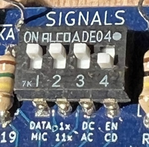
NinoTNC A4 setting
Set the SIGNAL switch to 1110, DATA radio (1v p-p Tx Audio), 1x receive audio amp, DC coupled, audio DCD enabled.
Turn the TX DEV to about 90%, i.e. just shy of fully clockwize.
Turn the TX DELAY to about 50% and then test to reduce.
- Conception, proof of concept, analysis, initial test, declaration of success, by KK4HEJ
- PCB connection locations, chassis penetration, more analysis by N2IRZ
- Cable dressing, web page and photography by KA2DEW
 This annotated image shows attach points for PTT, TxAudio, RxAudio.
 Test penetration of the CAT5 wire into the chassis.
If your cable doesn't fit, pick the next larger drill bit and enlarge the hole.
Put the top cover and CAT5 wire asside until a later step.
Test penetration of the CAT5 wire into the chassis.
If your cable doesn't fit, pick the next larger drill bit and enlarge the hole.
Put the top cover and CAT5 wire asside until a later step.