NinoTNC and Vertex FTL-1011, 2011, 7011
Construction requires:
- ruler marked in 1/8" or better precision
- 5' CAT5 cable
- soldering iron
- earphone plug 3.5mm parts-express 092-158
- RJ45 connector
- RJ45 crimper
- 2-inch piece of 1/4-inch heat shrink tube parts-express 080-624
- DE9 male connector parts-express 090-550 + hood parts-express 090-695
Obtain 5foot CAT5 wire.
DE-9 end
Strip back 3/4" of the outer jacket from one end of the CAT5 wire.
RJ45 end
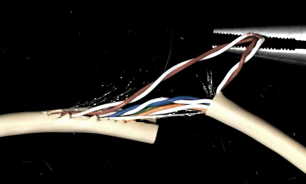
Strip back 18" of the outer jacket from the one end of the CAT5 wire to prepare the earphone plug twisted pair.
Note: Using a box cutter, cut around the outer jacket of the CAT5 at 18" from the RJ45 end.
Next, using diagonal cutter, cut the outer jack toward the RJ45 end about 2".
Pull out the brown and white&brown pair from the 18" end so the outer jacket will easily slide off
click to enlarge
|
|
Both Ends
On both ends, cut and dispose of brown, white&brown, white&blue wires.
RJ45 end
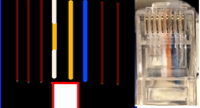
On the RJ45 end (18" end), Trim the orange, white&orange and
blue wires back to 5/8" from end for RJ45 connector.
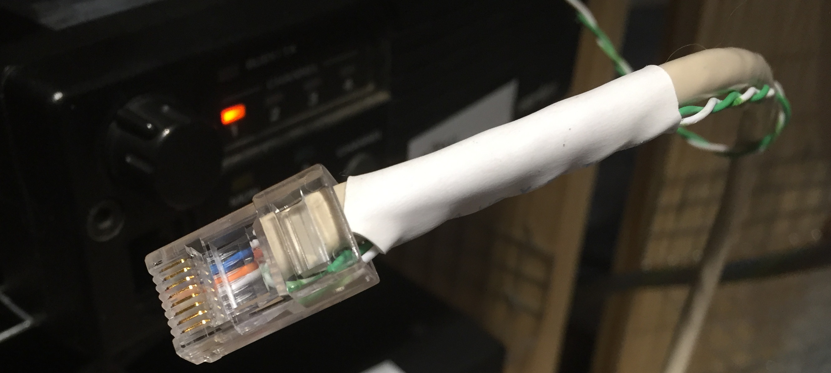
Fold back the 18" long green and white&green pair. Place a 1" long heat shrink
over the CAT5 and green pair. -- don't heat the shrink yet. Note: See photos below of heat shrinked end.
|
Insert 3 conductors + folded back end of green and green+white
wire into RJ45 and crimp such that the blue, orange, white&orange wires
are as shown to the right and down below.
|
|
DE-9 end
The length of the wire from the RJ45 to the DE-9 end depends on where the TNC's DE9 is to be located.
I suggest making sure the Vertex radio is turned off or unplugged from power.
Now temporarily plug the RJ45 into the radio, and then route the CAT5 wire through your cabinetry to the back of the NinoTNC.
Leave an extra several inches to take corners and whatnot.
Unplug the RJ45 from the radio.
Strip back about 3/4 of an inch of the remaining CAT5 jacket.
Untwist the brown wire pair.
Cut the brown-white wire back to the CAT5 jacket.
Cut the brown wire back to about 1/8" from the CAT5 jacket.
Strip the orange, white&orange, blue, green, white&green to 1/4".
Twist white&blue, white&green and white&orange wires together.
These are the ground wires.
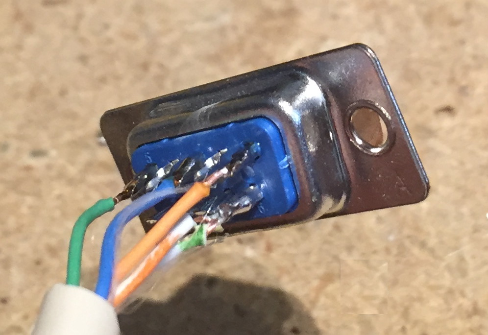
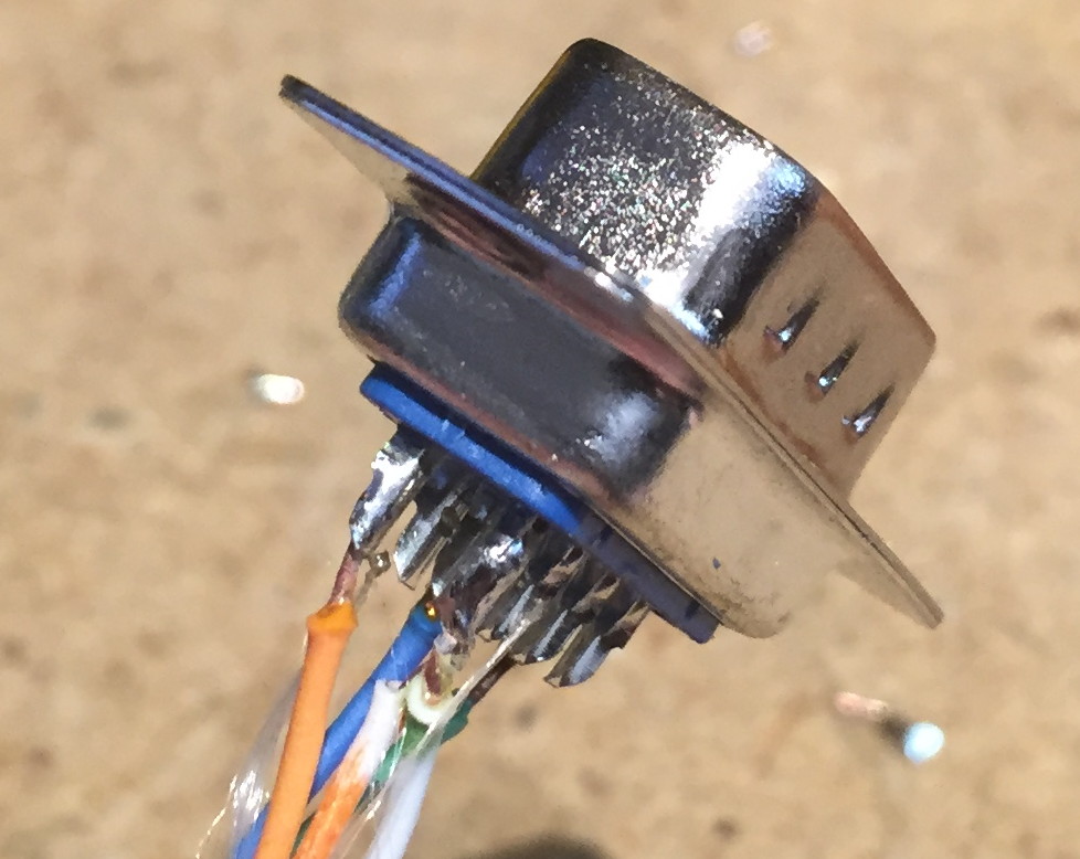
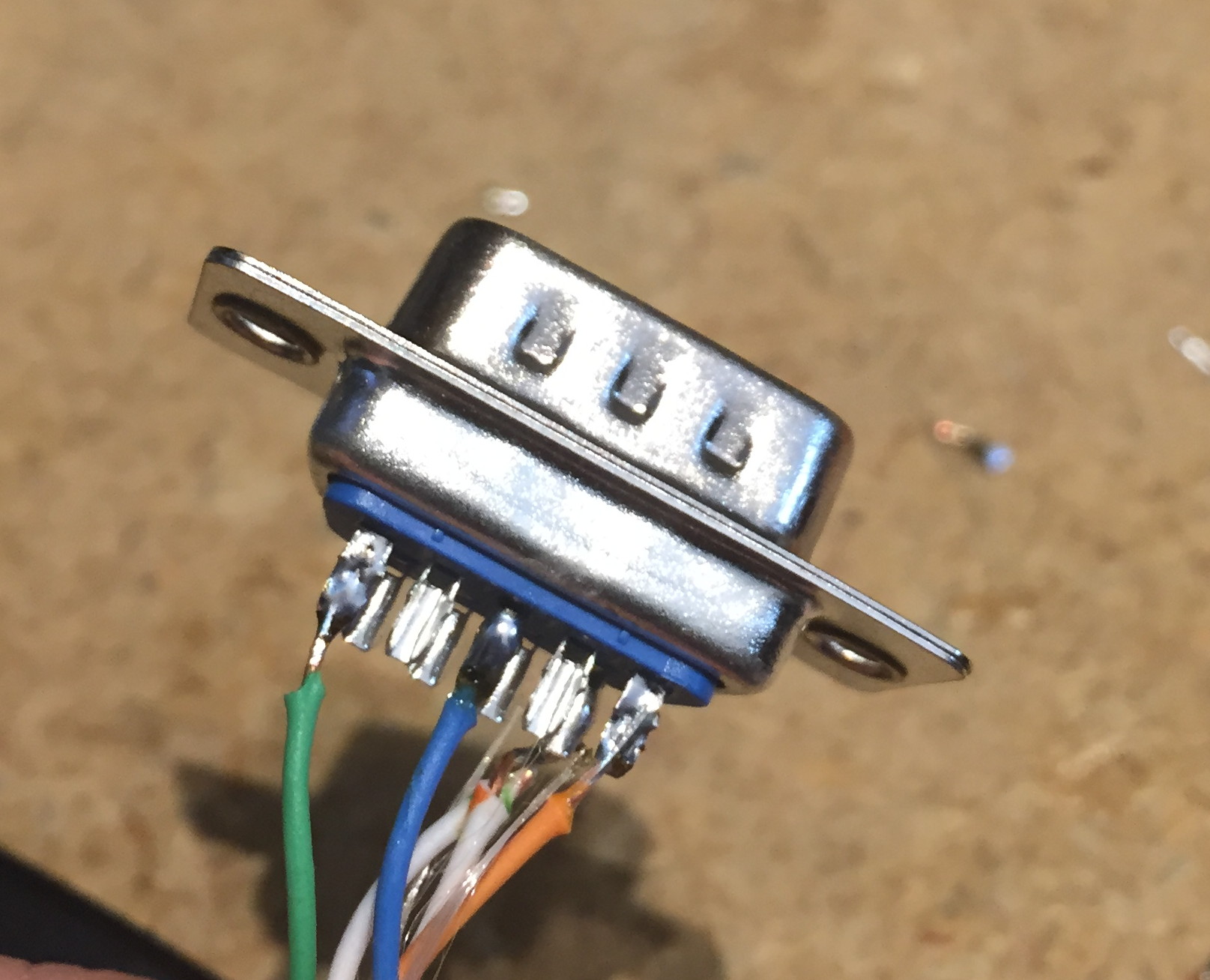
Tin, trim (to remove spurious untwisted bits) and attach the twisted pair to DE-9 as per drawing.
Tin, trim and attach green, blue, orange wires to DE-9 as per the drawing.
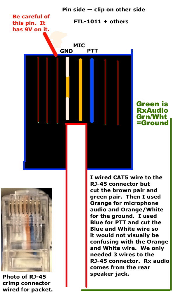
Note: MIC is the same as TxData for our purposes. Speaker jack center conductor becomes RxData. The ground from
the speaker jack must be connected to the Microphone Ground and both are soldered to pin 6 on the DE-9 connector.
This drawing is of the solder cups on the back of the radio-cable DE9 from the perspective of the inside of the D-sub Shell.
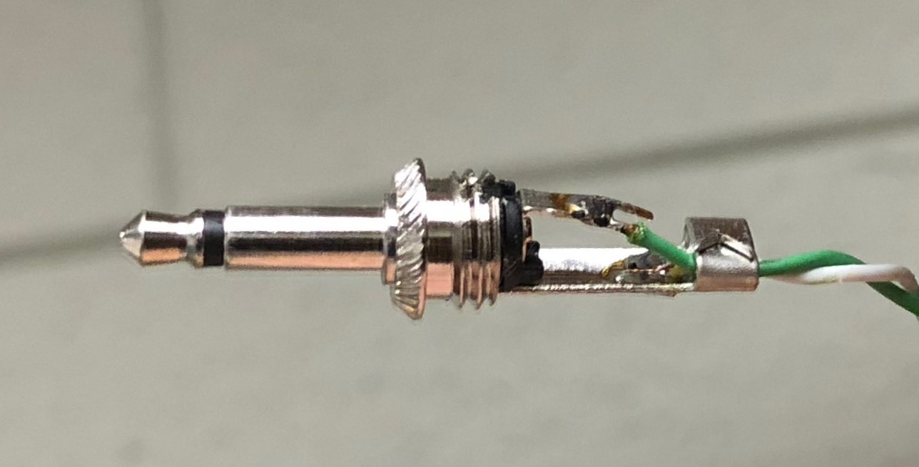
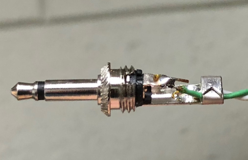
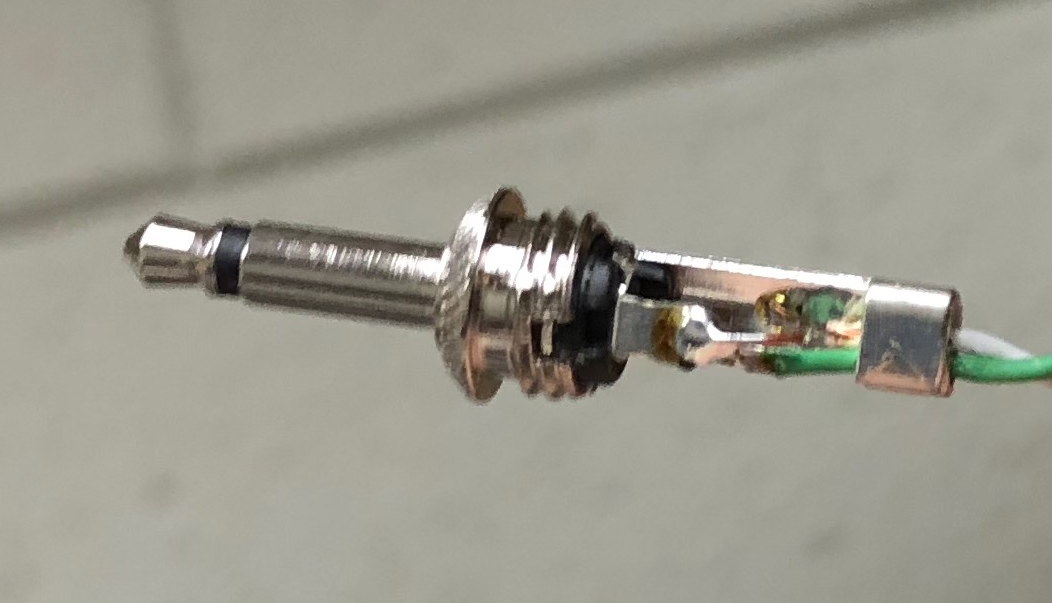
Earphone plug
Solder 18" long green wire to center conductor of earphone plug. Solder white&green wire to ground of earphone plug.
Note that reversing these two wires on the earphone jack is the number one cause for failure of this cable!
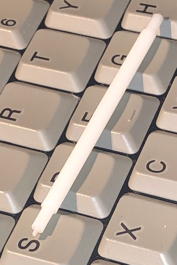
Where applicable, make sure you put the plastic insulator, spring, and screw-on cover over the wire, in the proper order and orientation, before soldering!
Alignment Procedure
For FTL-1011 99 channel LCD display 6m radio.
Requirements:
- A signal generator capable of repeatably selecting an output level in the -60dBm to -125dBm range.
It would be nice if it could generate a 1khz tone at selectable modulation widths.
- wattmeter for 50watts on 51Mhz
- dummy load for 50watts continuous duty on 51Mhz
- Phillips head screwdriver.
- Small flat head screwdriver.
- radio adjustment tool.
I'll try to find a part # for this.
If you know the part # and source, please email me.
Procedure
- Attach 8-pin Vertex mike-to-DE9-connector programming-cable between the radio and an MSDOS PC.
- Run CE7 software.
- Apply power to the radio.
- Read the contents of the radio. This contents is called a Code-Plug (named for the ROM chip that contained the code and needed to be plugged inside the radio, in late 1970s).
- Note the frequency of the First IF in the software.
The default is 16.9mhz.
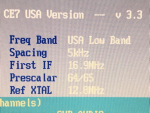
If different, you'll want to retain the new value when writing the Code-Plug to the radio.
If the radio is programmed with the wrong IF, the receive frequency will be offset from the programmed frequency and you'll have to figure out by how far and then reprogram the radio using the proper IF frequency.
- Write a new Code-Plug setting a set of memories to 44, 46, 48, 50, 51, 52, 53, 54 mhz.
This will be used for tuning the PLL lock for RX and TX.
- Disconnect the programming cable.
- Turn the radio over so most of the heatsink is on the bench, and remove the large plastic cover by unscrewing it from the back of the radio through the heatsink.
Note that the top cover is a smaller plastic piece and inside of the top cover is the PL tone level, Mic gain adjustments.
The Rx alignment and both RX and TX PLL tuning are done through the larger cover on the bottom.
- Remove the metalic cover from the bottom.
This will require unscrewing 5 identical phillips head screws.
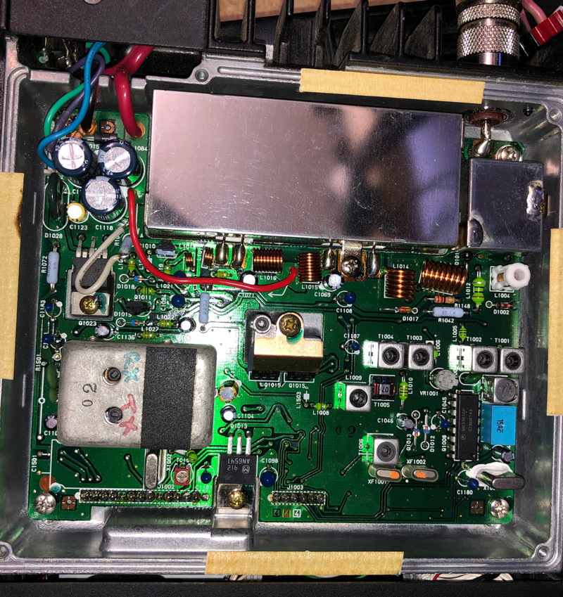
- Important note: If there is a small circuit bolted to the inside of the metalic cover and wired to the board and rear-panel speaker connector, you will have to remove that circuit.
This circuit was used to put some kind of digital signal or tone pulse onto the receive audio connector.
I would love to know why.
It is only on about half of the radios I've worked on.
Check the speaker output with a scope while in a few steps.
You can proceed with the alignment procedure, but the radio will be useless on packet until you remove that modification.
Audio-Mod Removal-Instructions linked at the bottom of this page.
- Attach the signal generator to the coax connector.
- Adjust the signal generator to 44mhz and -80dBm signal strength.
- Note the RX signal through the radio speaker.
- Move the signal generator to 46mhz and change the radio channel to follow.
- Step again and again until the radio no longer hears the signal. This should happen at about 50 or 51mhz.
- Find the PLL lock can.
This is a 1" x 1.5" metal can which is on near the front of the bottom circuit board, near the "A" button end of the radio.
Use an indelible magic marker to write "RX"near the adjustment hole toward the rear of the radio and "TX"near the adjustment hole toward the adjustment hole toward the front of the radio.
- While listening on the lowest frequency of the lowest frequency where receive failed, tune the RX PLL lock adjust counterclockwise one or two rotations or until receive becomes active.
- Step the radio and signal generator up one channel and repeat.
- Repeat this step until the radio receives on 54Mhz.
If the radio does not work on 54Mhz, step back down the frequencies and re-adjust.
Your goal is to have the radio receive on at least 50Mhz through 53Mhz for packet radio.
If the radio does not receive at 53Mhz and 54Mhz it will probably not be useful for voice operations on the east coast where repeaters output at 53.01 through 53.99.
Packet radio, however, is between the high end of 50Mhz and the middle of 51Mhz.
- Now set the radio channel to 51Mhz and the signal generator to match.
- Set the generator to the lowest output level where the signal can be heard reliably but noisily. This is probably between -80dBm and -100dBm.
- Put your tool into T1004 and peak the receive quieting. Readjust the signal generator so the signal is again reliable but noisy.
- Again re-adjust T1004 for best receive quieting.
- Repeat in T1002 and then T1001.
- Disconnect the generator -- we are done with it for this radio.
- Attach a microphone to the radio and a watt-meter with dummy load capable of supporting and showing 50watts or more.
- Set the radio to 44Mhz and key the microphone.
- Step through your test channels and find the highest frequency where the radio delivers measurable power.
This should be from 44Mhz to 48Mhz and possibly up to 51Mhz. If there is no transmit power measured on any channel, this radio is out of the scope of this document.
- Your goal will be to get the radio to transmit on the 50Mhz, 51Mhz, 52Mhz and optionally the 53Mhz channels.
The radio should transmit at 40watts or above at 50 through 52Mhz and maybe reduced to as low as 25Mhz at 53Mhz.
- Set the radio on the lowest frequency above 46Mhz where the radio does not transmit.
You'll need to unkey and re-key the radio to test the output and hear the beaps.
The radio should beep through the speaker if you key up out of lock.
- While keying and unkeying on that lowest channel, slowly turn the TX PLL lock counterclockwise.
You should only have to turn it one full rotation to move the lock frequency by 2Mhz.
Beware that on some radios the adjustment ferrite will come out of its transformer while turning in the counterclockwise direction.
Pay especially close attention to this because if you lose the ferrite or get it stuck in the can, you will have difficulty.
- Move the radio up one channel and repeat.
- When you reach the highest frequency where it locks, or fails to lock, move the channel back down to 50Mhz and make sure it still locks there.
- When turning the adjustment clockwize, be aware that the ferrite will break if it reaches the full extention in that direction.
Don't do that.
- Set the squelch level VR1001 so the squelch closes on noisy signals.
- Put the metalic cover back on and screw down with 5 screws.
Note that the squelch adjustment is available through a hole in the metalic cover.
- Put the plastic cover back on and screw down with 1 screw through the heatsync.
Dead memory-retention battery
Supposedly the batter is a standard button cell but I've never seen this, and I am told that it is a pain to replace.
If the cell is dead, the radio will always come up on the lowest channel in the lowest bank, by default.
However, there is a menu called Common>Miscillaneous where you can set the
Switch on channel to the bank and channel # of your choice.
minimum volume
One of the menus allows you to set a minimum volume. I recommend against that. Set it to 0.
Writing to the radio
On my 233Mhz MSDOS computer, writes to the radio are very difficult.
The radio frequenty dumps out of the write and asserts a failure.
This is because the computer and program are too fast for the radio.
The radio was programmed with an old MSDOS computer and the programmers apparently assumed that the radio would always be able to keep up.
The only way to work through this is to do the write over and over until it works.
On my computer that can take 10 minutes or so worth of try and fail and try again.
Audio Mod Circuit Removal
W4RFQ made some notes with photos on how to remove this circuit.
I've never done it successfully but several other local hams have.
One ham said that he couldn't fabricate the 3 pin header thing and just soldered the wires to the existing header.