| home | builders | Search |
| builders ➜ Radios & Wiring for Radios ➜ TK-760/762(H) 9600 Baud Mod |
This page describes the signal locations and component change to allow the Kenwood TK-760-series (including TK760H, TK-762 and TK762H) radios operate at 9600 Baud reliably. These instructions do NOT refer to the "G" versions. We also assume that a NinoTNC will be used with it.
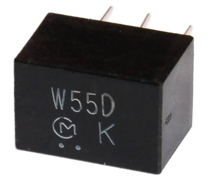
The critical task is to replace one of the receive ceramic IF filters with a wider-bandwidth version. This radio offers two programmable bandwidth selections, "FM" and "NFM", with standard IF 6dB bandwidths of 12 kHz (Type "F") and 9 kHz (Type "G") respectively. We need to install an IF filter of Type "D", with a bandwidth of 20 kHz. This very slightly decreases receive noise performance and selectivity, but in Amateur applications these are more than acceptable compromises. The biggest obstacle to performing this is the absolute requirement for a de-soldering iron.
Additionally, all of the needed signals for 9600 Baud operation are readily available, except for direct access to the transmit modulator circuit, which requires soldering to the PC Board at a relatively easy-to-access location.
Before starting, verify that the radio operates and programs normally.
To perform this modification, you’ll need:Start by removing the top and bottom covers of the radio (4 screws each). From the top of the board, remove the IF shield (6 screws). Turn the radio to work on the bottom.
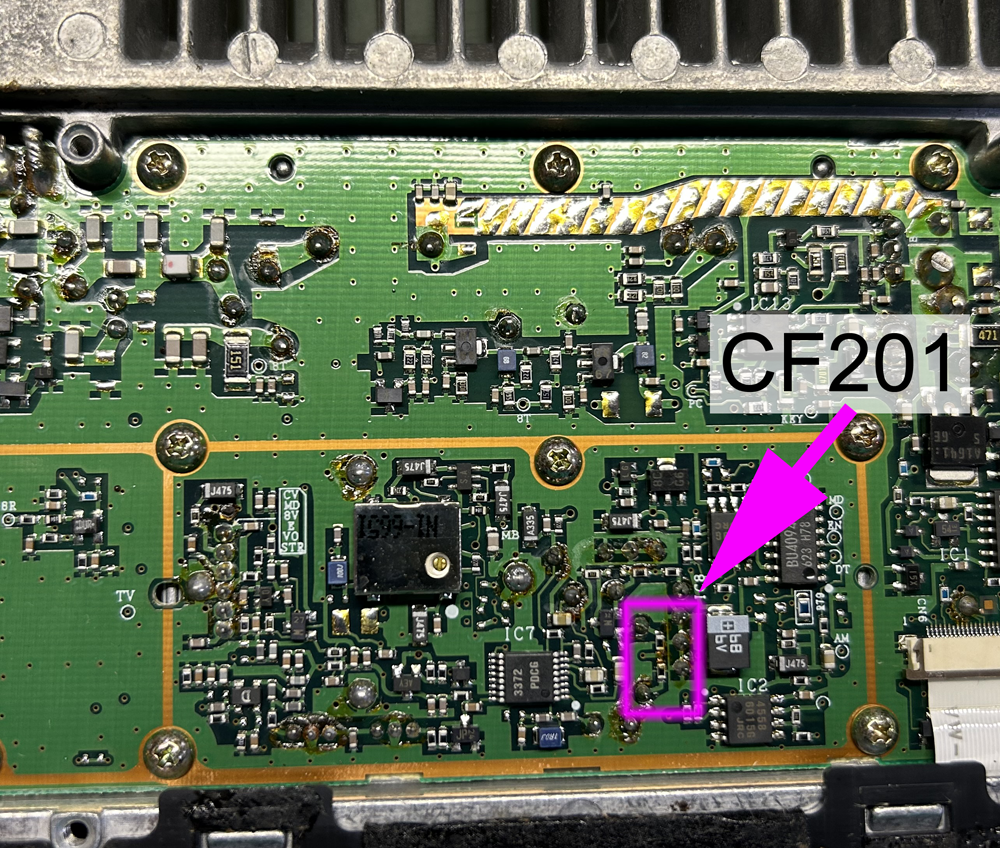
We will replace the "Wide" IF ceramic filter with a wider-bandwidth version. Start by locating and desoldering all five pins of CF201(F). Note that without a desoldering iron, this is considered impossible without fatal damage to the radio.
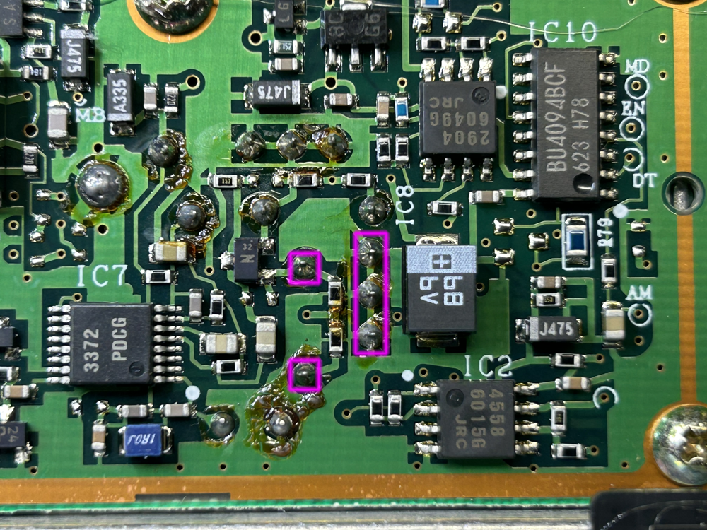
Remove the original component, then install and solder the replacement. Make sure all five pins pass through the board before soldering, these pins bend easily.
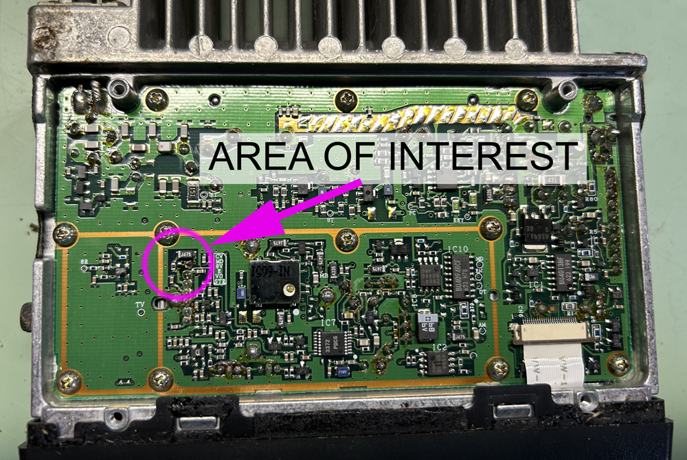
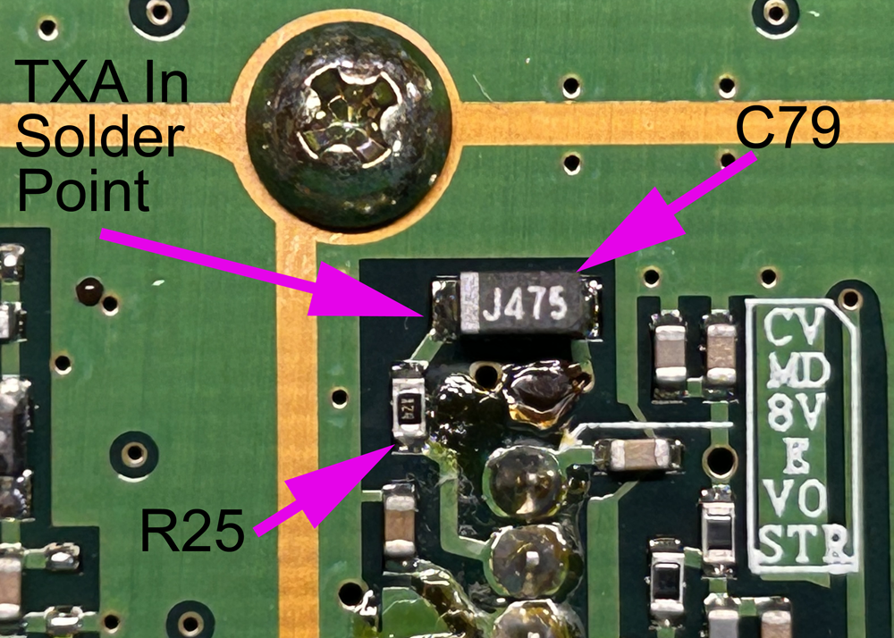
Still on the bottom of the PC board, identify the components C79 and R25, and the solder point for the Transmit Audio (TXA) Input.
Strip one end of the 30 AWG wire-wrap wire about 1/16" – strip off more than that, then cut it to length.
Solder the stripped end of the wire-wrap wire to the intersection of C79 and R25 as shown. One end of C79 offers a good place to solder.
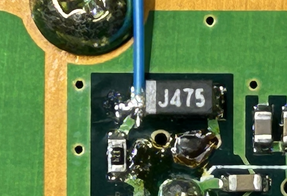
Generously hot glue the wire to a spot a half inch or so from the solder connector to act as a strain relief.
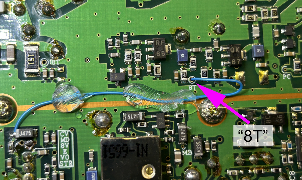
Locate the through-hole marked "8T" and carefully route the wire-wrap wire through it to the top side of the board. Be particularly mindful to feed the wire through cleanly – the sharp edges of the through-hole can easily strip off the insulation from the wire. Leave some slack in the wire.
Generously hot glue the wire near where it passes through the board.
Reinstall the bottom cover of the radio using 4 screws.
Prepare the 4-conductor wire by stripping about 2" of the outer insulation, then strip 3/16" of each individual wire’s insulation and tin the ends.
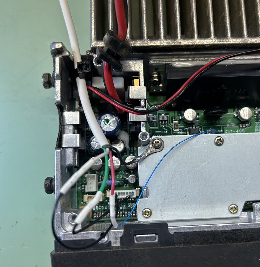
Pick a wire color to be the Ground (GND) signal to the TNC (black in the photo) and solder the ring terminal to it.
Turn the radio over to the top, then reinstall the IF shield cover using 6 screws. Place the GND ring terminal under one of these screws and tighten it.
Pick a wire color to be the Transmit Audio (TXA) signal from the TNC (red in the photo). Place a 1/ 2" piece of thin heat-shrink tubing over the wire-wrap wire from the other side of the board, strip the end about 3/16", then solder the wire-wrap wire to the TXA wire. Slip the heat shrink tubing over the connection and shrink it in place.
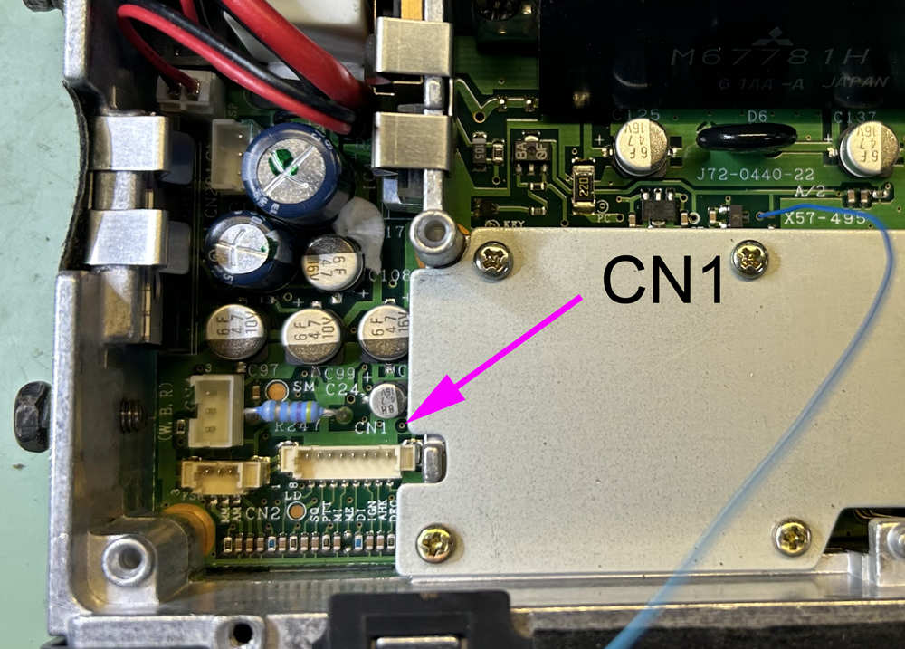
Prepare the contacts for CN1, which should be pre-crimped with a few inches of wire. Strip the bare end of both wires about 3/16" and tin them. Insert one contact into the connector body in position 1 (DEO signal), and the other in position 7 (PTT signal). In the image below, one contact is inserted into position 7. Positions 1 and 8 are marked on the PC board.
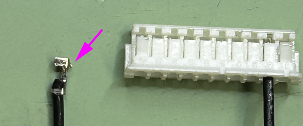
Look closely at the not-installed contact above: One side has a small ‘locking nib’ sticking out (arrow), which must be positioned to the front of the connector body, the side visible in the photo. These contacts will work their way out if not inserted properly: After inserting, give each a gentle tug to verify it is locked. Hot melt glue can help if you can’t get it to lock.
Pick a wire color to be the Push-To-Talk (PTT) signal to the TNC (white in the photo). Place a 1/ 2" piece of thin heat-shrink tubing over the wire, the solder it to the wire coming from position 7 of the CN1 connector. Slip the heat shrink tubing over the connection and shrink it in place.
Pick the last wire color to be the Receive Audio (RXA) signal to the TNC (green in the photo). Place a 1/ 2" piece of thin heat-shrink tubing over the wire, the solder it to the wire coming from position 1 of the CN1 connector. Slip the heat shrink tubing over the connection and shrink it in place.
Write those colors down so you don’t forget! All four wires should be connected to something.
Insert the CN1 connector into the CN1 receptacle on the radio. Small pliers may help.
Lift out the radio’s power cord and grommet from the slot at the rear of the radio. Leaving some slack in the 4-conductor wire to the TNC, place the zip-tie on it tightly so that it acts as a strain relief, then cut off the excess.
Place it into the slot, then reinstall the power cord grommet.
Reinstall the speaker spider, speaker and top cover, making sure to avoid pinching any of the wires.
On the free end of the 4-conductor cable, attach the TNC connector.
For a NinoTNC, the DE-9 Male connector pin connections are: Pin 1 (TXA, red), Pin 3 (PTT, white), Pin 5 (RXA, green), Pin 6 (GND, black). Pin 9 can also be connected to GND but it is not required. Install the connector hood.
Program and test the radio, then verify TNC operation.