| home | builders | Search |
| builders ➜ Antennas ➜ Gamma Match for a Yagi |
A Gamma Match is a way to convert a (relatively) high impedance antenna segment to a 50 Ohm unbalanced (coaxial) feed line. It is often used for Yagi directional antennas. On this page I describe the construction and dimensions for Gamma matches for 144 MHz, 222 MHz and 440 MHz.
You don’t necessarily have to build your own gamma match, although I feel it is the least expensive option. If you prefer, simply buy a driven element and gamma match assembly from Arrow Antennas. As of April 2025, for their ‘solid element’ antennas this would cost around $15 for 2 meters and $12 for 440, without buying their (expensive) gamma shorting bar (easily made at home). For 220, the parts aren’t listed but I bet a phone call will get you what you need.
Note that these ingredients are suggestions, and have been tested successfully, but if your on-hand stock is a little different, be confident that you can get it to work with a bit of fiddling.
Ingredients
(see table for lengths):
This gamma match is intended to be used with a standard NBS-type Yagi. Specifically, the boom is aluminum, 3/4” to 1” in diameter, and the elements are electrically connected to the boom. Ideally use 3/8” or 1/2” tubing for the driven element; all other elements can be as small as 3/16”, but remember that you need a way to fasten them to the boom. I prefer 1/2” tubing, through which I can drill and use No. 6 hardware to fasten them to the (cross-drilled) boom.
Table of lengths
| Item | 145 MHz | 222 MHz | 445 MHz |
|---|---|---|---|
| Outer Tube | 6.5" | 4.5" | 2.5" |
| Bare Copper Wire | 7.5" | 5.5" | 3" |
| Plastic Sleeve | 7" | 5" | 2.5" |
These dimensions are not critical, as there is a lot of adjustment possible. If you are going to make an error, too long is the direction to go. For 144 MHz, I have seen outer tubes as small as 4”, and for 440 as long as 3”. If the outer tube is way too long, you can always cut of most (not all – keep some for future retuning) of the excess.
What these three parts (outer tube, plastic sleeve, and inner wire) do is create a variable capacitor in the low (10-100) picofarad range, which is used to tune out any reactance in the antenna. The highest capacitance is when the inner and outer conductors are fully engaged, meaning the assembly is at its shortest length. If you need to reduce capacitance, you slide the outer tube out from around the wire. The choice of plastic sleeve material does affect the capacitance slightly, as does its presence between the inner and outer conductors, but in general this effect is small and easily kept constant.
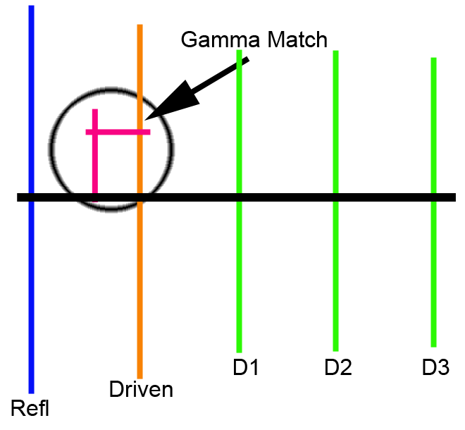
This image shows the main elements of a gamma match:
*It is possible to build the gamma match using a variable capacitor, then substituting in a fixed-value capacitor in its place. However, this unnecessarily complicates things, so while possible, I don't recommend it.
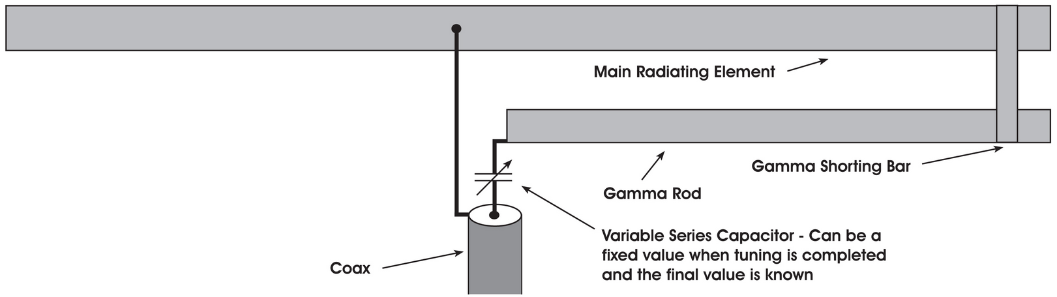
The gamma shorting bar also plays a critical role, but is easily fabricated. Its only job is to provide an RF path between the outside of the gamma rod and the driven element. A DC path is not really necessary, but for stability of the capacitance value it is best to exclude moisture from these connections. The position of the shorting bar along one side of the driven element affects the impedance of the antenna seen by the coaxial cable.
By adjusting the impedance and nulling out reactance, you affect the SWR of the antenna, with the goal of reducing SWR to a minimum at your desired operation frequency.
Connector Bracket
Start by making the antenna connector mounting: Cut a piece of aluminum sheet around 1-1/4” wide and around 3 inches long. At one end, drill holes for the connector: Drill the center hole 5/8”, and at least two of the four mounting holes for #6 hardware. Measure your connector for its actual dimensions!
The bend point (dimension “X”) depends on the diameters of the Driven Element (DE), aluminum Gamma tube and antenna boom. The goal is for the DE and Gamma tube to be exactly 1-1/2” from each other as shown.
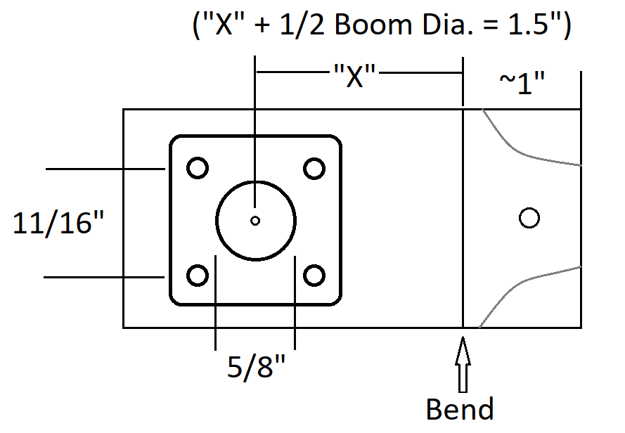
They also need to be one above the other, so consider your bend direction and mounting so that is the case. In the image to the right, if the bracket were bent to the left (instead of the right as shown) perhaps a single screw could have been used for the DE and the bracket. Give this some thought! Also, how will your coaxial cable be run, towards the center of the antenna (mid-mount) or the end (end mount)? Make sure your connector faces the right direction!
Calculate the bend point, add 1/16” (longer), then bend the bracket – the bend takes up some distance! If you have a vise, use the jaws to hold the bracket at the bend point then use your hands to bend it over
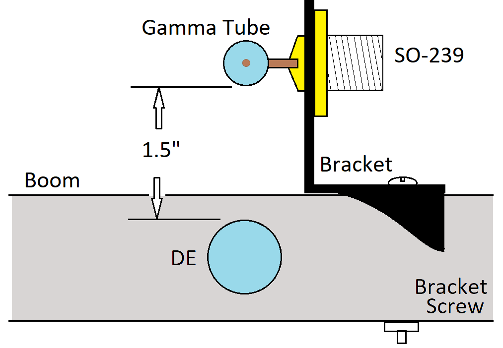
If your DE is not in the center of the boom, that’s fine: Wherever it is, just get the DE and Gamma tube 1.5” apart, and one directly above the other.
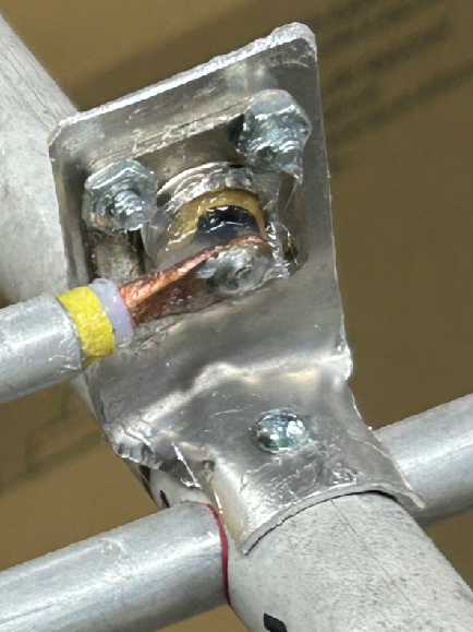
Drill a hole for the boom screw about 5/8” from the bend, then bend the corners down (pliers and hammer) so it fits snugly against the boom. See the photo for an example of a finished bracket.
Using Coaxial Cable Instead of Wire & Sleeve
If you decide to use a piece of coaxial cable with the outer covering and shielding removed (instead of the separate inner wire and plastic sleeve) the instructions below still mostly apply. The coax must NOT be the type with a foil shield beneath the braided shield, and must have a solderable (copper or copper-clad) center conductor. Instead of flattening the copper wire as described below, which might be impractical for stranded conductors, you can solder a small ring terminal to the end, which would then be soldered to the connector’s center conductor, OR you can bend the wire end to fit directly into the connector’s center conductor hole for soldering.
Copper Wire
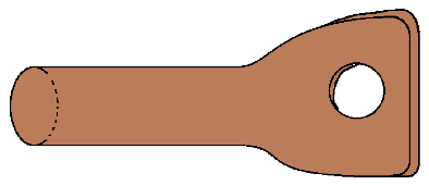
Cut the bare copper wire a bit long according to the chart. Using a hammer, flatten about 1/2” of one end of the heavy bare copper wire. Hit it on both sides to help keep the flat centered on the round wire. Drill a hole in the flattened end so it fits over the SO-239’s (or N) center pin, about 5/32”. If you look past the silicone sealant in the photo above, you can see the flattened end. Trim the flattened end so about 1/8” of copper remains past the hole. Trim the other (untouched) end to total length according to the chart. On both ends, use a file and/or sandpaper to remove all sharp points and corners: it should not be able to pop a latex balloon (RF hates sharp edges).
Shorting Bracket
Cut two pieces of the aluminum sheet around ½” wide and 3” long. (If you like, the shorting bracket can be made from relatively thick – like 1/8” – material, but you’ll need a plan to bend it, as it’s significantly harder to bend neatly. The advantage is that more clamping force can be applied to the antenna elements). Bend one end of both pieces to fit snugly around the driven element (DE) tube. Use a solid rod, the same diameter as the driven element, as a form for the bending. You can use a bolt, drill bit, or anything suitable. The goal is for the bracket ends to clamp onto the driven element tube. The two bent ends should not touch – leave a gap. Also allow for a gap between the pieces. These gaps ensure some clamping force can be exerted on the tubes.
This shows the first bend in a top and side view.
Next, measure 1.5” from the start of the DE bend, and bend the other end of both brackets to the size of the Gamma tube. Again, use something solid as a form. Trim any excess from the end. Then drill a hole for #6 hardware and assemble it loosely. Your bracket should end up looking like this:
Remember that we want a gap between the brackets so we can tighten it against the DE and Gamma tube, as it needs to grip both tightly. See the two photos below, which are examples of shorting brackets. If all copper is used, they can be soldered permanently.
Two examples of shorting brackets.
Solder the Wire
Place the flattened end of the copper wire over the pin on the SO-239, point it so it is parallel to the DE, and solder it. Keep it as far away from the connector body as practical: You do NOT want it to short against or otherwise touch the connector body.
Assemble The Gamma
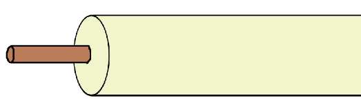
Slide the plastic tube onto the copper wire most of the way, checking for fit. If the tube is loose against the copper wire, add some heat shrink to the copper wire to take up the gap (or, ideally, get different plastic tube). (If using coax, this doesn’t apply)
The aluminum Gamma tube ends need to be flat and smooth: If you used a plumbing-type pipe cutter to cut the tube, that tool has crushed the end of the tube inwards slightly, which is not OK. Use a file, deburring tool, or whatever you have, to get the ends of the tube to be the same inside diameter as the rest of the tube.
Then slide the aluminum Gamma tube onto the plastic tube a bit, again to check for fit. As with the plastic tube, if there is any gap or play, try to fill it with heat shrink on the plastic tube. Remember that both the plastic tube and the Gamma tube need to be able to slide easily, so not too much heat shrink, but try to avoid any air gap!
Now add the Vaseline. You can use electronic-grade silicone grease (not silicone sealant!) instead, but don’t use anything else! Some greases will attack the plastic. Some greases are conductive (like NoAlOx or Ox-Gard), which is bad. Pull off the Gamma tube and plastic tube. Grease the copper wire generously, then slide the plastic tube on it again, as far onto the copper wire as it will go (which should almost touch the SO-239).
Repeat this for the Gamma tube, again being generous with the grease. Its purpose is to keep out water for as long as the antenna is in the air. While water getting in to the Gamma match assembly is not terrible – the plastic (and heat shrink, if any) still insulates even when wet – excluding water is the right thing to do. Slide the Gamma tube to about 1/2” from the SO-239 connector, being sure it is well away from the copper wire.
Place the bracket halves onto the DE and Gamma tube and hand-tighten the screw, allowing it to be able to slide but not on its own. For now, locate the bracket about an inch from the boom.
Adjust The Gamma
All of the above was simply to create a capacitive coupling between the SO-239 and the DE. Now we have to adjust two things to get the SWR on the desired operating frequency as low as possible: The distance that the aluminum tube overlaps the copper wire (slide the aluminum tube in and out) and the location of the shorting bracket (slide it in and out). These two adjustments interact with each other, so it becomes a matter of adjust and measure, repeat until satisfied.
Start with the outer tube fully inserted over the inner wire, almost touching the SO-239 connector, and the gamma shorting bar an inch or less from the boom, lightly tightened so it can slide but not move on its own.
Place the antenna at least a wavelength (2 meters = 7 ft, 70 cm = 28 inches) from anything conductive – farther is better. Purists are correct to state that this is still too close, but we’re just adjusting SWR, so the bad effects are minimal. Run the coax from the antenna away at a 90 degree angle from the boom.
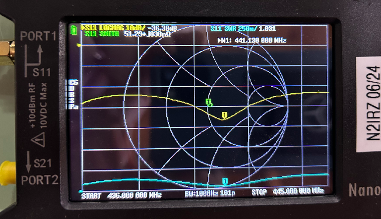
The ideal tool for adjusting a Gamma match is a Vector Network Analyzer, but an SWR meter is generally sufficient. I use a NanoVNA, more than adequate for this purpose. Its greatest benefit is the ability to see the SWR over a frequency range without needing a transmitter, as opposed to an SWR meter which requires transmitting for each measurement, and being blind to where the lowest SWR frequency is.
Set up the VNA to plus and minus about 8-12 MHz from the desired operating frequency and calibrate it for the S11 channel (the S21 channel is not used), meaning Open, Short and Termination. Include the coax to the antenna in your calibration routine; the open, short and termination take the place of the antenna itself for calibration. This means, the open, short and termination are connected at the far end of the coax, in place of the antenna. We want to measure and adjust the antenna, not the coax.
One VNA channel should be SWR, one should be Return Loss. I also set one channel as LogMag and the 4th channel as a Smith chart, but these are optional.
Connect the antenna and observe the SWR dips by frequency. You’ll see a repeating series of dips in SWR, at, above and below the design frequency. Adjusting the Gamma match won’t pull those frequencies by much either way, but there is some room to pull the dips up or down in frequency a bit.
If there is an SWR null visible on or near your desired frequency, or in the next steps you get one close enough to your operating frequency, re-calibrate the VNA to be plus or minus 2 or 3 MHz from your desired operating frequency. This offers better sensitivity to your adjustment effects.
If you are using an SWR meter, measure the SWR on the desired frequency by using the lowest possible transmit power. Then make the adjustments described below, checking the SWR after each adjustment.
Now, move the shorting bracket out away from the boom about half an inch, step far away from the antenna, and note the effect on SWR at your frequency (take notes!). Continue this, 1/2” at a time, until you’re near the far end of the aluminum tube. Place the bracket at the spot where the lowest SWR at your desired frequency was seen, and mark that location on the DE.
Hold the shorting bracket from moving along the driven element. Slide the aluminum Gamma tube out around 1/2” further from the boom, and check the effect. Repeat like the above. It gets tedious, but you should be able to find a spot where the tube position gives you a good result. Then vary the shorting bracket and tube locations by 1/4" or less to fine-time it.
Now, repeat the shorting bracket adjustment for minimum SWR/highest return loss, moving it 1/4” at a time now, and mark the best position on the DE. Then, repeat the gamma tube adjustment again. These two adjustments interact, so you might need to repeat these a few times. But once the SWR is reasonable – less than 1.5:1 – you’re done. Yes, you can spend another hour to wring out another tenth, but it makes little practical difference.
MARK both the bracket and tube final positions! I also write the tuned frequency on the boom, near the mounting bracket, for future reference.
If necessary, don’t be afraid to start over. Sometimes the antenna tunes up quickly and easily, sometimes it fights you every step. But if it’s working well, narrow the VNA’s range as mentioned above.
Here we see a NanoVNA displaying the SWR (aqua, measured at 1.031:1), LogMag (yellow, also known as return loss) and a Smith chart (green, showing near-perfect matching at the 50 Ohm point) over a 9 MHz bandwidth (436-445 MHz). Note that only Port 1 (S11) is used for these measurements.
Ending
Once you have the adjustment where you want it, tighten the shorting jumper and make one final check to see if it moved. If all is well, put a few dabs of silicone caulk on the DE, Gamma tube and where the Gamma tube meets the plastic tube…and leave overnight so everything gets locked in place.
The next morning, use silicone (or latex) caulk generously to seal and hold everything together. Once that cures, give everything a light coat of Vaseline to offer additional water protection. If you have a suitable rubber or plastic end cap for the Gamma tube, use it.
Troubleshooting
If necessary, you can increase the resonant frequency of an antenna by shortening the elements. Work in ¼” increments or less, start with the DE but also include the reflector and first director. Cut a bit off one side of one element at a time, then check and adjust. Go slowly, as it is a pain to add something back
You can also lower the resonant frequency by lengthening the elements (DE, reflector and 1st director) by adding something conductive to the end of an element: A small piece of wire, smaller tubing to go inside the larger element, even aluminum tape. As with shortening, try ¼” at a time, on one end of one element at a time. Once you get where you need to be, make those added bits more permanent with screws, rivets, etc. I often drill a small hole in the element and run a screw or 1/8” aluminum rivet through it to fasten an over-long bit of aluminum wire which can be trimmed as needed.
The DE and Reflector have the greatest influence on resonant frequency. The first 2 or 3 directors also have some influence. Further out directors have progressively less influence. When adjusting lengths, start with the DE, move to the Reflector, then the first direction. If still problematic, go back to the DE and repeat.
Photos
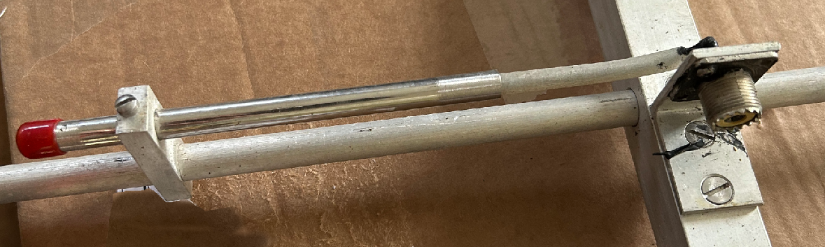
This gamma match on 223 MHz did not need much adjustment at all. It could have been longer though.
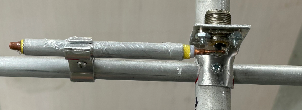
Here we see a commercial Gamma match on a 440 MHz antenna. It was retuned to 430 MHz; again, not much tuning needed, although it was sensitive and was moved in 1/16” increments.
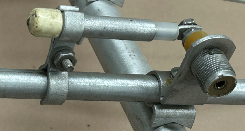
Another way of handling a gamma match. The presence of the coaxial cable somewhat parallel to the driven element (and other elements) will affect the antenna pattern, so try to minimize the length of the parallel cable. 90-degreen connectors are evil – they tend to have poor impedance continuity – so avoid those.
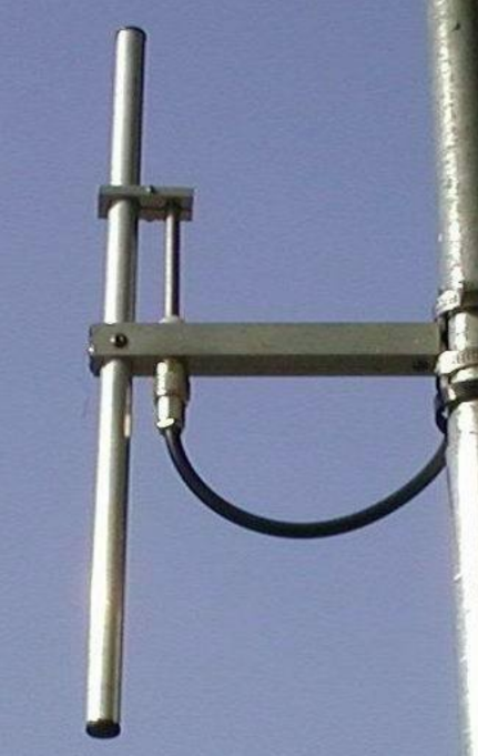
A 2 commercial 2 meter antenna’s gamma match.
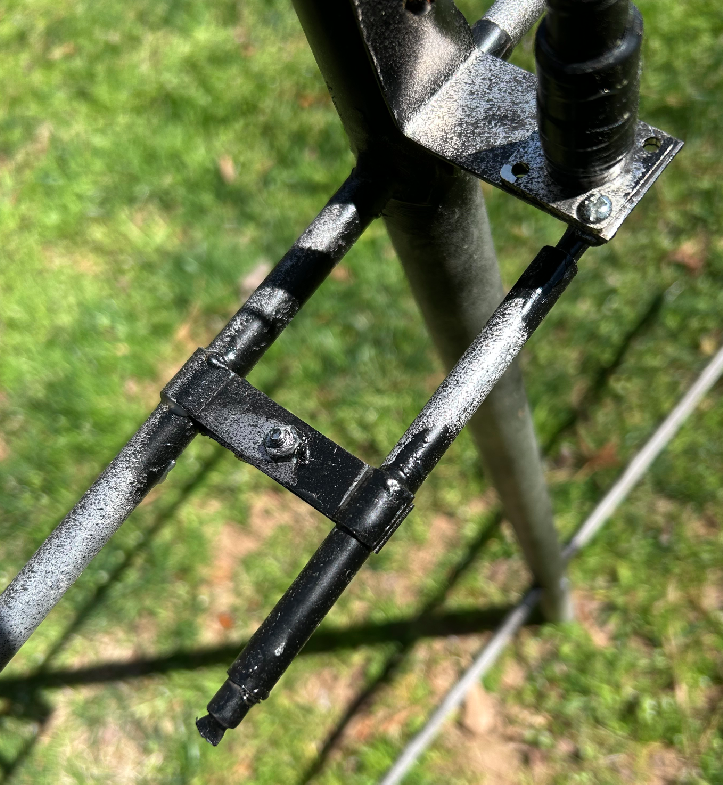
A homemade gamma match on a 2m antenna, complete with ‘camouflage’ paint. Note that the outer tube is fully engaged with the inner wire – this gamma assembly should have been an inch or two longer for easiest adjustment.
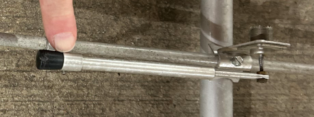
Another 2m commercial antenna’s gamma match. The finger points to the shorting bar. Note how the inner wire is fastened to the connector, using nuts and washers.