NinoTNC to Kenwood TK8180 (and TK7180)
The TK8180 is available in a common K (type 1) version and an uncommon K2 400-470mhz version.
The K (type 1) is meant for 450 to 520 mhz and will work at the top end of the UHF ham band.
The K2 covers the entire ham band and is highly desirable and hard or expensive to find.
The TK7180 covers 136-174mhz and is only available in a K (type 1) model.
The radios are programmed using Kenwood KPG-89d, running on MSWindows, and a USB to RJ45 connector cable available on eBay.
I use MSWindows 7 emulated using Parallels Desktop 14 on a MacOS Mini running MacOSX 10.15 Catalina.
I measured 15 of the TK-8180-K units at greater than 25 watts and about -105dBm for dead-full-quieting receive, at 441.5mhz.
They seem to be available on eBay for well under $100 each.
Beware that some people are selling these with password protection which I have not been able to get around.
The TK8180 can run 9600 baud to another TK8180 using NinoTNCs, at short range, using the back-of-radio connector.
It's quite fast in terms of switch speed and has nice features with monitor speaker and volume control.
However, as of July 2020, it doesn't seem to do 9600 even over a short real link without lots of retries.
It does work at 4800 over several-mile-long links with the NinoTNC.
Even with noisy distorted (by multipath reflections) it still sustains 2400 pretty well.
This information is intended for the UHF K radio.
I expect the codeplug to work in the K2 radio as well, but you'll want to set channels across the low end of the band to take advantage of the wide coverage.
Important... always read and save the existing working codeplug (channel data) from a commercial radio before overwriting it.
I would save it as filename tk8180-b2430023 (serial number of the radio).
This way if a configuration is required because of an odd feature or version, you will be able to rescue the radio.
After you do that you are pretty safe in putting your own or borrowed code-plug into the radio.
Do not set a password on the radio.
That's a good way to get yourself locked out.
Most of the K radios work as low as 441.5, and up to the top of the ham band.
Some of the K radios work as low or lower than 440mhz.
You'll have to test yours to find out.
If you know a way to extend the frequency range of the K radio lower than you find it, I would like to hear from you.
The linked codeplug programs the radio with channels every 25khz from
440 to 441.475,
445.45,
446.025-446.500.
Each channel is programmed twice, once in high power, and once in low power.
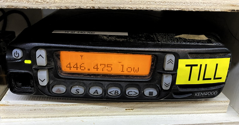
The radio's text display will show channel frequency, or channel frequency and "low".
The radio is programmed to connect the rear panel connector to bypass audio, removing the mike amp, and bypassing the speaker amp.
The speaker is live but the squelch is fully open.
The volume control adjusts the speaker volume but doesn not affect the data output RXA signal.
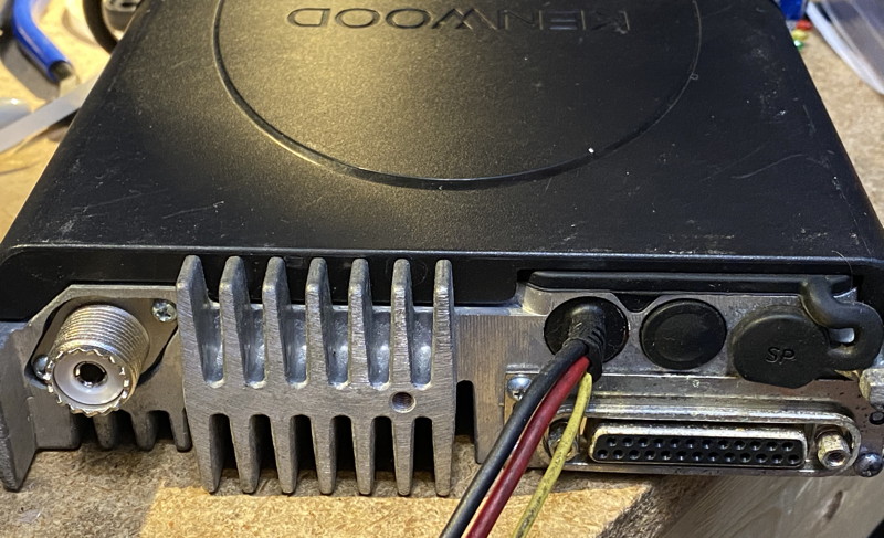
Connect the 25 pin DB25 on the back of the radio to the TNC using the cable described below.
Use the codeplug linked here.
Here is the code-plug data to be loaded into the TK8180 using KPG89d software.
You should control or right click on this link and download this data file.
Codeplug data file
This cable will connect to a TK8180 configured as per the codeplug linked above.
Construction requires:
- soldering iron
- hookup wire (CAT5, 14inches for NinoTNC along side the radio)
- DE9 connector + hood
- DB25 connector + hood
- tie-wraps, 3"
When I build this cable, I use CAT5 wire.
I used the solid color wires from CAT5 as an example.
The striped color wires can be left not-stripped and balled up in the shell making sure they don't conduct with any pin on either connector.
If your DE9 and DB25 shell hardware kit doesn't properly secure the wire against slippage, use the tie-wraps to keep the wire from pulling through the hardware by
wrapping the tie wrap around the wire on both sides of the clamp.
I'm not particularly worried about shielding or using the twisted ground wire here because the audios and PTT are low impedance with a good voltage swing, and the wires are not very long.
They are unlikely to be interfered with by RF.
It could be better to add green stripe and blue stripe wires soldered at one end in addition to the brown GROUND wire (to the same pin 7 as the brown), but I would not recommend this unless you have trouble.
Diagram of DE9 connector
This drawing is of the solder cups on the back of the radio-cable DE9 from the perspective of the inside of the D-sub Shell.
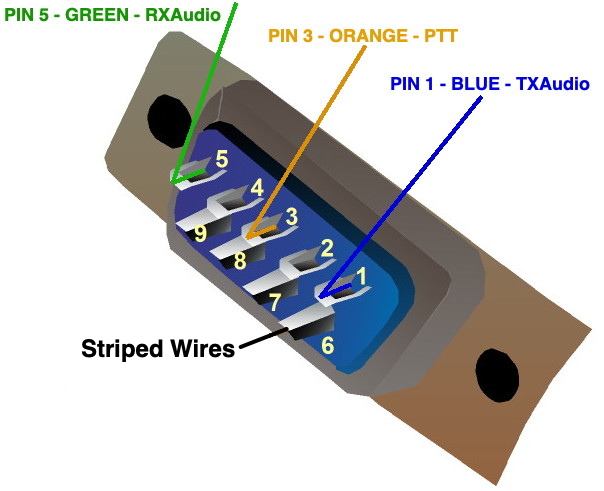
The row of 13 pins is numbered pin#13 on the left and #1 on the right.
Pin 5 (5th from the right) is
BLUE and is TXAudio.
Pin 7 (middle pin) is
BROWN and is GROUND
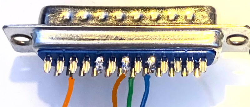
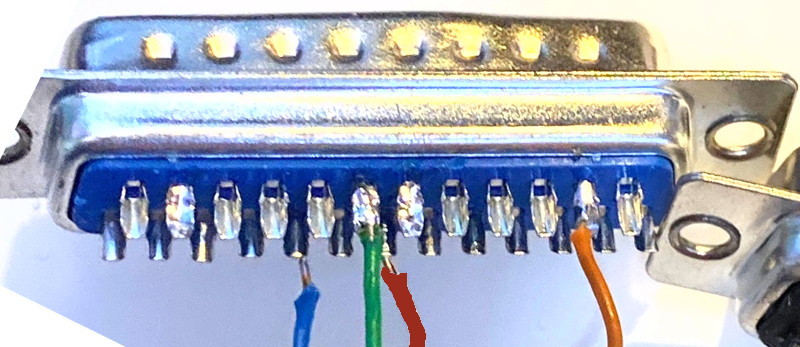
Here I flip the DB25 over so we can see the row of 12 pins.
The row of 12 pins is numbered #14 on the left and #25 on the right.
Pin 19 (6th from the left) is
GREEN and is RXaudio.
Pin 24 (2nd from right) is
ORANGE and is PTT.