Maxon SD-125 Programming
Programming and Configuring the Maxon SD-125 Series Radios
Jim WB2LHP My email is good in
QRZ
The radios are programmed via the DB-9 connector using a simple interface and Windows-based software.
There are settings for TX frequency, RX frequency, H/L power, hang time, TOT, power save mode, BCLO and more.
The radios are very flexible. Here are the important links you will need.
In order to program this unit you will need buy or build a programming interface.
The programming interface has two connectors, one which goes to your computer, and the other to the SD-125 transceiver.
The computer interface given in the schematic is RS-232 but you may connect that to a USB to RS232 adapter to attach to a modern MSWindows computer.
Programming Interface
This is the link to the full Maxon SD-125 series service manual.
Download the software for MSWindows:
[rfwiz.com] MAXON software link
There is a squelch adjustment but it requires a separate programming interface and software (go figure).
I have found the factory setting to work fine with no issues and would not recommend going down this rabbit hole.
Once you have the Maxon programming software successfully loaded and configured, follow these instructions IN ORDER.
- Be sure the interface power is OFF
- Connect the interface to your serial port
- Connect the interface to your radio
- Launch the application
- Click FILE, NEW
- Select BAND
- Program each channel's information
- Click FILE, SAVE and name the file
- Click the RED (WRITE) transfer icon
- Software will prompt you to RESET POWER SUPPLY
- Turn interface power ON
- Software will show WRITE progress
- When WRITE progress reaches 100%, turn interface power OFF
You can verify programming by changing step 9 to BLUE (READ). Complete instructions are under the software HELP tab/Programming Manual. Be sure to proceed at your own risk. The interface I use with the changes I've made has worked flawlessly for me.
Alignment
In the service manual there is information on tuning the receiver and adjusting the Local Oscillators.
There is also an extender board to separate the Digital and RF PCBs which allows access to RF tuning adjustments.
These appear to be unnecessary.
With about 30 SD-125 activations for ham radio under our belt there were never any adjustments to the RF board.
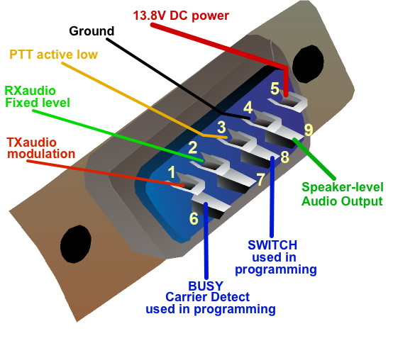
Connector Pinout
This is the full DE9 connector pinout from the perspective of the back of a solder-cup side of female connector you'll be wiring.
 Back to Maxon SD-125 page