G8BPQ Monitor of NODE command
In this page I verbosely explain what the information in the G8BPQ Monitor output means.
Access this output using a web browser on your node IP address followed by :8212
or by running QTterm and connect to your node with all of the monitor checkboxes clicked.
See also:
faq: Technical Packet.
See also:
builders:QT-Term.
See also:
builders:TARPN-MON.
See also:
builders:G8BPQ-Monitor: L2 retries and L3 chat fail.
Below I have a description of what a single user of the network was doing, a trivial map of the affected region of the network, a copy of the monitored messages, and then a message by message analysis of what the monitor trace means.
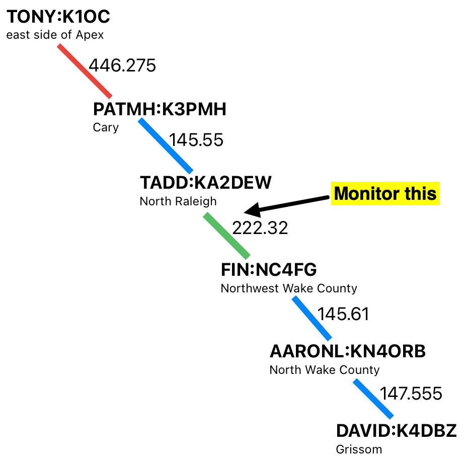
In this example, the station WA1QRM connects into the TONY:K1OC-2 node.
WA1QRM could be local at Tony's house, or could do this from across the network.
Either way, WA1QRM is now able to give commands to the TONY:K1OC-2 node.
WA1QRM does this command sequence.
c david.
nodes
b
From the perspective of WA1QRM's terminal, sitting at K1OC-2 node, this is what he sees:
c david
TONY:K1OC-2} Connected to DAVID:K4DBZ-2
Grissom, NC
DAVID:K4DBZ-2} I for commands
nodes
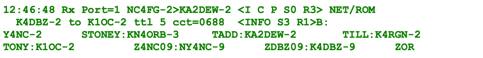
DAVID:K4DBZ-2} Nodes
AL187:WF4TAL-2 BBS:K4DBZ-1 BEN:KN4RFT-2 BOBS:W4TTX-2
DANIEL:AG4DB-2 DAVE:W4EIP-2 DOUG:N3LTV-2 ELIJAH:KO4BAC-2
ERIC:WO2S-2 FIN:NC4FG-2 KARL:K4LNX-2 PATMH:K3PMH-2
PAUL:KO4PZA-2 PIUSER:K4DBZ STEPHN:NY4NC-2 STONEY:KN4ORB-3
TADD:KA2DEW-2 TILL:K4RGN-2 TONY:K1OC-2 Z4NC09:NY4NC-9
ZDBZ09:K4DBZ-9 ZORB10:KN4ORB-10
b
Disconnected
The network map, showing only the links between TONY:K1OC-2 and DAVID:K4DBZ-2, looks like this:
Trafficked messages can be initiated at any site in the connected network and be delivered to any other site.
The specific details of how those messages are delivered is described in several hard-to-read documents.
One superpower that we have here, and granted by G8BPQ's LINBPQ node-stack application used by the TARPN system, is an analysis, in real time, of the messages sent between the node sites.
The real time analysis is provided on a Telnet port provided by LINBPQ on port 8011.
Several devices may Telnet to that port at a time so more than one view into the node activity can be operated simultaneously.
A program provided by G8BPQ and others to view this output is
QT-term-TCP.
Another is TARPN-MON by WA2M.
TARPN-MON is a standard feature of a TARPN install and may be accessed using a web browser to the node's IP address on port 8212.
So in my case, the URL I enter into the web browser is 10.0.0.200:8212.
Hopefully, with this document and a few others, we may be able to get around having to read the hard-to-read documents, by showing real examples of how the network delivers traffic across many stations/sites/nodes.
We'll try to use correct network terms so if you do want to read and understand the hard-to-read documents, we won't have confused or oversimplified the issue in ways that make your job more difficult.
Consequently, some of the hard stuff is presented here, along with a summary of each step along the way.
The technical documentation is linked from the TARPN FAQ page under
Technical Documents about Packet Radio.
Terms:
Since the early 1980s, network machine design has mostly followed a model described by the Open Systems Interconnection group at the International Organization for Standardization.
This could be a lead-in to yet another hard-to-read document.
The good news is that a really nice graphic exists, created hundreds of times in fact, and you can view it here:
OSI network model.
The OSI model describes Layers of a network control/support stack made up of layers.
Layer 1 describes the hardware of a network node.
Layer 2 "Link" would be the description of the protocol (organization of the message) that passes between neighboring node stations in transmitted packets.
Layer 3 "Network" describes how messages are addressed to go from one network node to another network node, possibly many neighboor to neighbor hops away.
Layer 4 "Transport" describes the packaging of the message such that it can get to the destination, and, in our case, also allows for the message to be broken up and sent across multiple packets.
Layer 2 Data Link messages only go over the radio from one station to a neighbor station and the Layer 2 traffic is using IL2P which is a modified version of AX.25, first used in 1984.
The Layer 3 Network/Layer 4 Transport messages are carried by the Layer 2 Data Links.
Layer 3 Network/Layer 4 Transport messages, used on our network and by LINBPQ, are based on the NET/ROM protocol definition which was first published in 1988 or 89.
The Layer 3 Network/Layer 4 Transport messages are carried across a multi-link network on Layer 2 Data Link messages which are links between neighbor nodes.
The output from TARPN-MON and QT-term-TCP show a
monitor trace of the traffic seen by the local node site.
Only the messages transmitted or received by the radios/TNCs at that node are presented.
If we had a Monitor trace from each of the nodes, we could see each Layer 3/Layer 4 Network/Transport message crossing the network and the Layer 2 Data Link message from K1OC-2 to K3PMH-2 would have those callsigns, while the L2 message from K3PMH-2 to KA2DEW-2 would have those callsigns, etc.
In the Monitor trace, there are segments describing a single packet transmission or reception.
All of the packets are displayed starting with a timestamp and the comment
Tx Port= or
Rx Port=.
The first line of each segment discusses the Layer 2 part of the packet.
The Layer 2 message may or may not contain a Layer 3/Layer 4 message.
In this trace, all messages shown having more than one line contain a Layer 3 and Layer 4 part, and the trace shows both the Layer 2 information and the Layer 3/Layer 4 information.
In the G8BPQ LINBPQ software the presentation of the Monitor trace output conjoins the Layer 3 and Layer 4 information so we'll describe that output as Layer 2 and Layer 3 even though that's not completely clear.
Note: I use "L2" to describe the Data Link Layer (layer 2).
I use "L3" to describe combined Network and Transport layers (Layers 3 and 4).
I have to warn you that my education in this space came mostly in the hands of companies doing proprietary data communications, and working with ham radio data communications.
If somebody can tell me a better way of describing this stuff, I am listening.
The monitor trace shown here is from the perspective of the TADD:KA2DEW-2 node and showing only Port 1 of the TADD node which is the NinoTNC that faces the FIN:NC4FG-2 node.
After showing you the trace, all in one block, I will break down each line and discuss what is going on, and what the monitor text means.
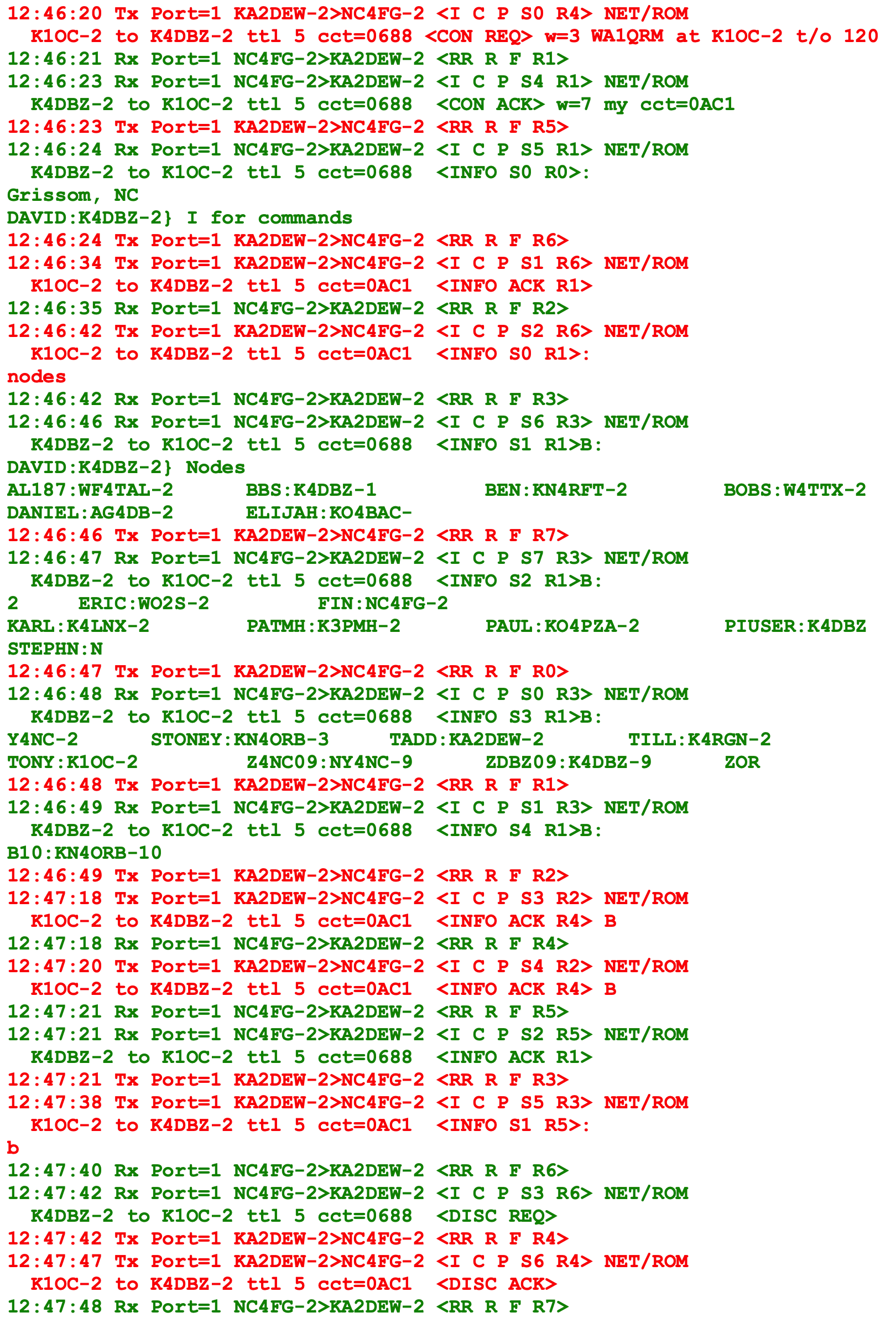
This monitor trace starts after WA1QRM connected to the K1OC-2 node.
In this trace, WA1QRM issues the a command,
c david.
The K1OC-2 node looks in its node data and sees that DAVID is K1OC-2.
K1OC-2 will generate a L3 message to the K4DBZ-2 node.
Below each block of text, I will describe what the block means.
01

This message shows that WA1QRM issued the command
c david.
When WA1QRM's command is seen by K1OC-2, the node looks in its network node list and sees that DAVID is K4DBZ-2.
K1OC-2 issues a L3 Network message to the K4DBZ-2 node to open a circuit between the two nodes to carry WA2QRM's traffic.
This Monitor trace shows KA2DEW-2 sending K1OC-2's message to NC4FG-2.
The first line of this segment shows KA2DEW-2 transmitting to NC4FG-2 and telling it that this is a Information and Command packet serial #0 "S0" and that KA2DEW-2 is ready to receive serial #4 "R4".
A Command is always answered by a Response packet, but it does not initiate a response.
The response is initiated by the Poll being set, or a timeout occurs at the receiving end.
Being an Information packet means that it will have a payload, either text or binary (binary means not straight ASCII-text).
In this case, there is a binary set of data that carries the L3 packet message.
The L3 packet is from K1OC-2 to K4DBZ-2 attempting to open a connection for K1OC-2's.
This L3 packet is originating from a different node and KA2DEW-2 got it on a different radio port.
KA2DEW-2 is serving as a relay in this case and is passing the L3 packet to NC4FG-2 who will continue passing it on to get to K4DBZ-2.
The routing of the L3 packet is not explicit in this message, but knowing the network map, and seeing the callsigns displayed from the L3 packet, we can figure this stuff out.
What
is in the L3 packet, is
- the two callsigns,
- circuit index of 0688, and with
- a remaining time-to-live of 5,
- a timeout of 120 seconds,
- a window size of 3, and
- the callsign of the commanding station, WA1QRM.
- a redundant and misleading indication of "at K1OC-2"
More description please
First, back to the L2 packet.
The text of the L2 packet shows
12:46:20 Tx Port=1 KA2DEW-2>NC4FG-2 <I C P S0 R4> NET/ROM
12:46:20 The timestamp is added by the Raspberry PI that is generating the Monitor Trace output.
This is not a clue as to the time of the message origination and it may not be synchronized to the other stations or to the real time.
It is useful for observing the amount of time it takes between traffic flowing out and back, for instance.
We can also time how long it takes for a complete file to be send and acknowledged.
Tx Port=1 This tells us that LINBPQ node software (also known by the author's callsign - G8BPQ) is transmitting this traffic to its port number 1.
For TARPN purposes, this means LINBPQ is transmitting on its first NinoTNC,
/dev/ttyACM0, or
/dev/ttyUSB0, depending on your NinoTNC type.
If your TNCs are defined using the port11 or port12 specification, then LINBPQ will call them Port=11 or Port=12.
KA2DEW-2>NC4FG-2 This callsign the LINBPQ node program is transmitting this packet with is the first of the two callsigns
The second callsign is being sent in the packet to get the attention of that callsign's station.
In a TARPN system the second callsign will be of a TARPN node which runs LINBPQ.
<I C P S0 R4> This is the "Control field".
It is 8 bits long. The contents of the control field slightly complex in that there are 3 different kinds of L2 message to be sent.
In this specific case, this is a I frame.
That means it has a payload of information, outside of the L2 header.
The payload here will be the L3 packet message, also called a 'frame', which just means that it has a particular start and end within the L2 packet.
The meaning of the letters in the Control Field display are:
- I - this means we're looking at an INFORMATION frame
- C - this is a command message -- there is also a response message (unless the circuit times out!).
- P - This is a poll message -- I'm not clear on what this does.
I think this means that we expect an acknowledgement, and the message would be repeated if the other end doesn't answer.
The other value of this same bit (F=final) means that we'll only send one copy and we don't need any acknowledgement.
- S0 - This says the message transmitter, KA2DEW-2, is sending a message with a sequential number of 0.
Next would be a S1.
In order to close out (finish?) this message exchange, the recipient would answer with R1, meaning it is ready to receive 1 and it has gotten message 0.
- R4 - This says the sender, KA2DEW-2 in this case, is ready to receive message 4.
If there were messages S0, S1, S2 from NC4FG-2, they have been finished and don't need to be resent.
Note that the S and R fields wrap from 7 to 0
NET/ROM This is an indicator that the L2 message PID (Protocol IDentifier) has byte=0xCF, meaning NET/ROM selected.
Any station receiving this INFORMATION Frame will know to handle it as a L3 NET/ROM statement.
L3 payload
The two callsigns in the L3 packet are K1OC-2 and K4DBZ-2.
K1OC-2 is attempting to open a circuit to send traffic to K4DBZ-2 node.
The traffic might not originate at K1OC-2 or end at K4DBZ-2 as it could be passing to or from further nodes at both ends.
All we know from looking at this trace is that WA1QRM got to the K1OC-2 node and instructed it to open a circuit to K4DBZ-2.
The
ttl time-to-live figure of 5 says that it the L3 packet that K1OC-2 has sent will be be disposed of and not relayed 5 hops down the line from this node.
In a TARPN system, with today's configuration package, the time to live defaults to 7.
It is being sent as 5 by KA2DEW-2, because the packet has already passed across two links.
See the map up above.
By the time this L3 packet is sent across the KN4ORB-2 to K4DBZ-2 link, the time-to-live will be at 3.
The
cct circuit index is a way for K4DBZ to know that this L3 connect request is a specific message that WA1QRM is starting.
It is possible for there to be many circuits from K1OC-2 to K4DBZ-2 and we don't want the contents of the messages from the different circuits to get confused.
Each circuit number is unique originating from one node.
The next L3 connect from K1OC-2 will get a different circuit number.
They are not sequential as far as I can see -- i think thit number that is used has more information than just the circuit number -- more research needed.
There is a timeout such that circuit numbers can be used again.
w=3 which should indicate that up to three L3 packets could be outstanding from K1OC-2, i.e. a second and third could be sent without waiting for the first.
The window does not apply to the connect request, i.e. when the connect request is still in flight and unacknowledged, K1OC-2 cannot start sending additional frames for this circuit.
The text "
at K1OC-2" is confusing and redundant.
This information is misleading as it makes it seem like WA1QRM is at K1OC-2 or originating his traffic from K1OC-2.
What it actually means is the same thing the from-callsign indicates at the beginning of the L3 line, and that is that the connect command itself to K4DBZ-2 was initiated after WA1QRM connecting to K1OC-2.
WA1QRM could be connecting into K1OC-2 locally, or could be counties away coming in across other network links into K1OC-2's command interpreter, and then requesting the connect to K4DBZ-2.
The
t/o Timeout figure is set in the G8BPQ configuration for K1OC-2 and describes how long K1OC-2 would wait for an acknowledgement of it's L3 packet, before it will send a retry.
02

This second message in the Monitor-trace sequence is marked as a Receive message from the other end of the KA2DEW-2 and NC4FG-2 link.
From a lack-of-detail [but correct] perspective, this message acknowledges the KA2DEW-2>NC4FG-2 L3 connect request just before.
Let's analyze so we can understand the detail.
The text of the L2 packet shows
12:46:21 This timestamp says this message is in the next second after the prior monitor-trace segment.
Rx Port=1 Receiving on Port 1, i.e. the same port as the previous message.
In this example Monitor trace, we are only watching port 1, which is convenient for analysis, but is not always the case in your adventures.
You'll need to pay attention to the port number in many cases.
NC4FG-2>KA2DEW-2 This callsign field is the opposite of the previous message, and indicates that this node, KA2DEW-2, is the destination for the received packet.
<RR R F R1> "Control field".
The meaning of the letters in the Control Field display are:
- RR - Receive Ready -- NC4FG-2 says it is ready to receive more data.
This also means that the L2 message is a Supervisory Frame.
There won't be an INFO payload.
- R - Response. This is an answer to the prior message from the other station.
- F - Final. This message will only be generated unless it is triggered by the neighbor. See AX.25 document
- R1 - This station has received the other station's S0 message and is ready for S1.
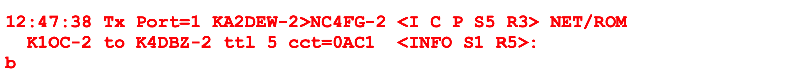
03

This message is K4DBZ-2 sending a connection acknowledgement to K1OC-2 for the requested circuit#
0688 and announcing K4DBZ-2's circuit#
0AC1
Let's analyze the L2 and L3 content of this message.
12:46:23 This timestamp says this message is in the next second after the prior monitor-trace segment.
Rx Port=1 Receiving on Port 1
NC4FG-2>KA2DEW-2 receiving traffic from NC4FG-2 to our node.
Note that NC4FG-2 might send a message we would hear, but is not addressed to our callsign.
In a TARPN, that could somtimes be a beacon/ID/status message.
Some of those messages might be recorded and used by this node.
Examples are node-routing broadcasts and TARPNstat messages (discussions for another help-file).
<I C P S4 R1> "Control field".
- I - This message has a payload section.
This doesn't say the payload is a NET/ROM.
That info is in the PID, not the Control Field.
- C - Command. In Layer 2, we want a response.
This isn't indicating we need a L3 response.
- P - This is a poll message -- I'm not clear on what this does.
I think this means that we expect an acknowledgement, and the message would be repeated if the other end doesn't answer.
The other value of this same bit (F=final) means that we'll only send one copy and we don't need any acknowledgement.
See AX.25 document.
- S4 - This message is serial#4 and we'll expect an R5 from the other end if it copies this message.
- R1 - This station has received the other station's S0 message and is ready for S1.
NET/ROM This is an indicator that the L2 message PID (Protocol IDentifier) has byte=0xCF, meaning NET/ROM selected.
Any station receiving this INFORMATION Frame will know to handle it as a L3 NET/ROM statement.
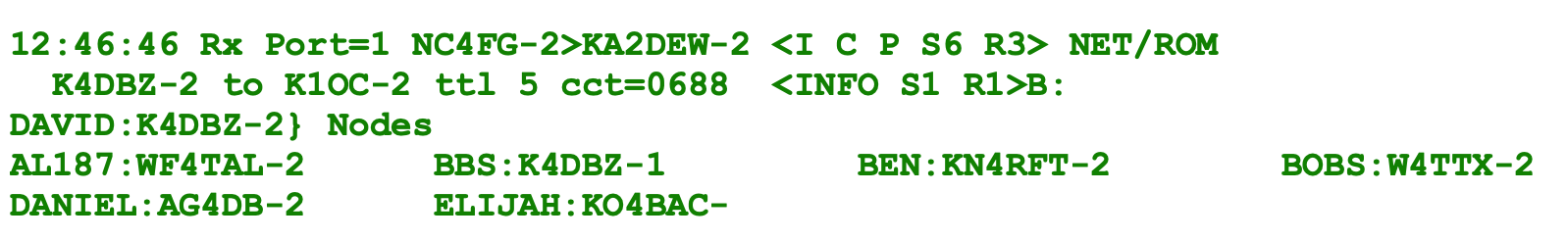
04

KA2DEW-2 is sending a response to NC4FG-2 announcing that it's receive serial number has moved on to R5 "R5" which tells NC4FG-2 that message S4 was received.
The text of the L2 packet shows
12:46:23 The traffic on this link is moving pretty rapidly.
Tx Port=1 Transmitting on Port 1.
KA2DEW-2>NC4FG-2 KA2DEW-2 transmitting to NC4FG-2
<RR R F R1> "Control field".
The meaning of the letters in the Control Field display are:
- RR - Receive Ready -- KA2DEW-2 says it is ready to receive more data.
This also means that the L2 message is a Supervisory Frame.
There won't be an INFO payload.
- R - Response. This is an answer to the prior message from the other station.
- F - Final. This message will only be generated unless it is triggered by the neighbor. See AX.25 document
- R5 - This station has received the other station's S4 message and is ready for S5.
05
This message contains the "Connect Text" from DAVID:K4DBZ-2 node.
The Connect Text is short enough that it fits in a single L3 payload.
Note the time stamp 12:46:24.
This L2/L3 message is received at KA2DEW-2, 4 seconds after KA2DEW-2 transmitted the L3 Connect request that started this Monitor trace.
This L2 message carries an L3 message from from K4DBZ-2 to K1OC-2.
The L2 message indicates it is sending serial#5 "S5" and again telling KA2DEW-2 that NC4FG-2 is ready for serial #1.
The L2 message also contains a L3 message as mentioned just above.
The L3 message is K4DBZ-2's circuit#
0688 sent as K4DBZ-2's L3 serial#0 "S0", while also marking that K4DBZ-2 is waiting for L3 serial#0 "R0".
The meaning of the letters in the L2 Control Field display are:
- I - This message has a payload section.
This doesn't say the payload is a NET/ROM.
That info is in the PID, not the Control Field.
- C - Command. In Layer 2, we want a response.
This isn't indicating we need a L3 response.
- P - This is a poll message -- I'm not clear on what this does.
I think this means that we expect an acknowledgement, and the message would be repeated if the other end doesn't answer.
The other value of this same bit (F=final) means that we'll only send one copy and we don't need any acknowledgement.
See AX.25 document.
- S5 - This message is S5 and we'll expect an R6 from KA2DEW-2 end if it copies this message.
- R1 - This station (KA2DEW-2) has received NC4FG-2 S0 message and is ready for S1.
For this kind of NET/ROM message, G8BPQ shows the bit field which includes Sent and Received sequence numbers, like the AX.25 bit fields.
The meaning of the letters in the L3 Control Field display are:
06

KA2DEW-2 is sending a reply to NC4FG-2 announcing that it's receive status has moved on to 6 "R6" which tells NC4FG-2 that message S5 was received.
The meaning of the letters in the Control Field display are:
- RR - Receive Ready -- KA2DEW-2 says it is ready to receive more data.
This also means that the L2 message is a Supervisory Frame.
There won't be an INFO payload.
- R - Response. This is an answer to the prior message from the other station.
- F - Final. See AX.25 document
- R6 - This station has received the other station's S5 message and is ready for S6.
07

This message transmitted by KA2DEW-2 carries K1OC-2's acknowedgement for the Connect Text message.
The meaning of the letters in the Control Field display are:
- I - This message has a payload section.
This doesn't say the payload is a NET/ROM.
That info is in the PID, not the Control Field.
- C - Command. In Layer 2, we want a response.
This isn't indicating we need a L3 response.
- P - Poll.
- S1 - This message is serial#1 and we'll expect an R2 from the other end if it copies this message.
- R6 - KA2DEW-2, again, telling NC4FG-2 that it has received their message S5.
The L2 portion is KA2DEW-2 L2 serial# S1 and the R6 states that KA2DEW-2 is ready for NC4FG's S6.
The L3 portion says it is sending over K1OC-2's circuit
0AC1 and stating that K1OC-2 is ready for S1 so it has received S0 sent at 12:46:24.
08

This message acknowledges the L2/L3 message most recently sent by KA2DEW-2 to NC4FG-2.
The meaning of the letters in the Control Field display are:
- RR - Receive Ready -- NC4FG-2 says it is ready to receive more data.
This also means that the L2 message is a Supervisory Frame.
There won't be an INFO payload.
- R - Response. This is an answer to the prior message from the other station.
- F - Final. See AX.25 document
- R2 - This station has received the other station's S1 message and is ready for S2.
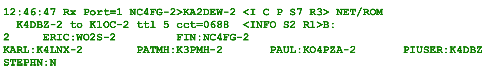
09
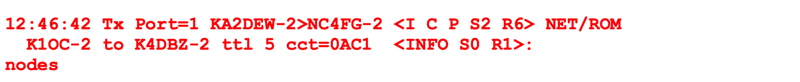
This message is carrying text
nodes in the L3 INFO frame from K1OC-2 to K4DBZ-2.
The L2 message says this is KA2DEW-2's S2 with a L3 message (NET/ROM) enclosed.
The L3 message is from K1OC-2 to K4DBZ-2 and is on K1OC's circuit
0AC1 as S0.
The L3 message has the payload text as indicated by the "INFO" tag and is redundantly stating that K1OC-2 is ready for K4DBZ-2 S1 L3 message.
The meaning of the letters in the Control Field display are:
- I - this means we're looking at an INFORMATION frame
- C - this is a command message -- there is also a response message (unless the circuit times out!).
- P - This is a poll message -- I'm not clear on what this does.
I think this means that we expect an acknowledgement, and the message would be repeated if the other end doesn't answer.
The other value of this same bit (F=final) means that we'll only send one copy and we don't need any acknowledgement.
- S2 - This says the message transmitter, KA2DEW-2, is sending a message with a sequential number of 2.
Next would be a S3.
In order to close out (finish?) this message exchange, the recipient would answer with R1, meaning it is ready to receive 1 and it has gotten message 0.
- R6 - This says the sender, KA2DEW-2 in this case, is ready to receive message 6.
If there were messages S0, S1, S2 from NC4FG-2, they have been finished and don't need to be resent.
Note that the S and R fields wrap from 7 to 0
10

NC4FG-2 is sending a reply to KA2DEW-2 announcing that it has moved it's receiver status to "R3" which tells KA2DEW-2 that S2 has been received.
This message acknowledges the L2/L3 message most recently sent by KA2DEW-2 to NC4FG-2.
The meaning of the letters in the Control Field display are:
- RR - Receive Ready -- NC4FG-2 says it is ready to receive more data.
This also means that the L2 message is a Supervisory Frame.
There won't be an INFO payload.
- R - Response. This is an answer to the prior message from the other station.
- F - Final. See AX.25 document
- R3 - This station has received the other station's S2 message and is ready for S3.
11
This message sends the first part of the NODE command response text from K4DBZ-2 to K1OC-2.
The L2 message says this is NC4FG-2's send serial number "S6" and is also stating NC4FG-2's receiver status is still "R3".
The meaning of the letters in the Control Field display are:
12

KA2DEW-2 is sending a reply to NC4FG-2 announcing that it's receive status has moved on to 7 "R7" which tells NC4FG-2 that message S6 was received.
The meaning of the letters in the Control Field display are:
- RR - Receive Ready -- KA2DEW-2 says it is ready to receive more data.
This also means that the L2 message is a Supervisory Frame.
There won't be an INFO payload.
- R - Response. This is an answer to the prior message from the other station.
- F - Final. See AX.25 document
- R7 - This station has received the other station's S6 message and is ready for S7.
13
K4DBZ-2 is sending the 2nd part of the NODE command response in a L3 message, passing over the network.
The L3 message got as far as NC4FG-2 and now NC4FG-2 is transmitting it to KA2DEW-2 as a payload in an L2 packet.
14

KA2DEW-2 is sending a reply to NC4FG-2 announcing that it's receive status has moved on to 0 "R0" which tells NC4FG-2 that message S7 was received.
The meaning of the letters in the Control Field display are:
- RR - Receive Ready -- KA2DEW-2 says it is ready to receive more data.
This also means that the L2 message is a Supervisory Frame.
There won't be an INFO payload.
- R - Response. This is an answer to the prior message from the other station.
- F - Final. See AX.25 document
- R0 - This station has received the other station's S7 message and is ready for S0.
15
16

KA2DEW-2 is sending a reply to NC4FG-2 announcing that it's receive status has moved on to 1 "R1" which tells NC4FG-2 that message S0 was received.
The meaning of the letters in the Control Field display are:
- RR - Receive Ready -- KA2DEW-2 says it is ready to receive more data.
This also means that the L2 message is a Supervisory Frame.
There won't be an INFO payload.
- R - Response. This is an answer to the prior message from the other station.
- F - Final. See AX.25 document
- R1 - This station has received the other station's S0 message and is ready for S1.
17

18

KA2DEW-2 is sending a reply to NC4FG-2 announcing that it's receive status has moved on to 2 "R2" which tells NC4FG-2 that message S1 was received.
The meaning of the letters in the Control Field display are:
- RR - Receive Ready -- KA2DEW-2 says it is ready to receive more data.
This also means that the L2 message is a Supervisory Frame.
There won't be an INFO payload.
- R - Response. This is an answer to the prior message from the other station.
- F - Final. See AX.25 document
- R2 - This station has received the other station's S1 message and is ready for S2.
19

20

21

22

23

24

KA2DEW-2 is sending a reply to NC4FG-2 announcing that it's receive serial number has moved on to 3 "R3" which tells NC4FG-2 that message S2 was received.
The meaning of the letters in the Control Field display are:
- RR - Receive Ready -- KA2DEW-2 says it is ready to receive more data.
This also means that the L2 message is a Supervisory Frame.
There won't be an INFO payload.
- R - Response. This is an answer to the prior message from the other station.
- F - Final. See AX.25 document
- R3 - This station has received the other station's S2 message and is ready for S3.
25
26

27

28

KA2DEW-2 is sending a reply to NC4FG-2 announcing that it's receive serial number has moved on to 4 "R4" which tells NC4FG-2 that message S3 was received.
The meaning of the letters in the Control Field display are:
- RR - Receive Ready -- KA2DEW-2 says it is ready to receive more data.
This also means that the L2 message is a Supervisory Frame.
There won't be an INFO payload.
- R - Response. This is an answer to the prior message from the other station.
- F - Final. See AX.25 document
- R4 - This station has received the other station's S3 message and is ready for S4.
29

30

See also:
builders:G8BPQ-Monitor: L2 retries and chat fail.
See also:
OARC WIKI packet:reading-traces
See also:
soundcardpacket.org Packet Radio Overview
See also:
soundcardpacket.org Deciphering Packet Frame Headers