Tait TM8105 Notes
Required Stuff
Required Software (Windows)
See Also
Power for the 25W version radios (identified by the BNC antenna connector) is supplied by a 4 pin molex connector on the back of the radio. Power for the >25W version radios (identified by the mini-UHF antenna connector) is supplied by a 4-pin Positronic DragonFly connector. Suitable power levels are 10.8 - 16VDC, with 13.8VDC being nominal.
Digi-key part number WM18435-ND works for the Molex connector, along with these contact inserts WM3112CT-ND .
Mouser part number 276-DF04F00/AA works for the Positronic connector, along with these contact inserts 276-FC114N2AA15650 (for 14-16 AWG; other sizes available).
Pigtail power connectors for the Molex version have also been seen on Ebay; search on "Tait TM8100 Power Connector" for options.
This blog post covers the programming really well. Some key notes repeated here for posterity.
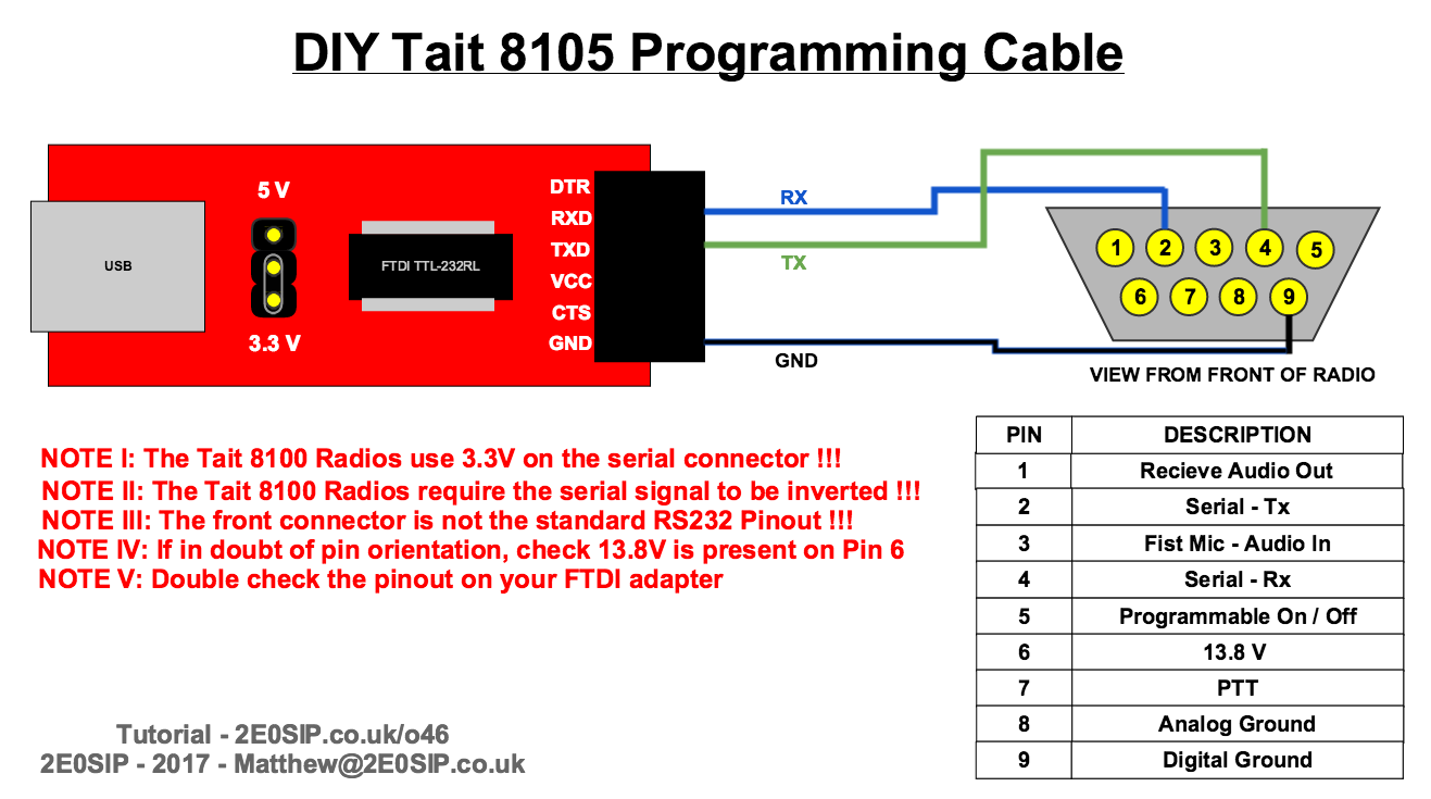
Programming is done using a Windows computer and a USB to serial cable. Ready-made programming cable are available on eBay, but they are pricey (considering what they are), about $35. A DIY solution is very approachable.
Since the Rx/Tx logic levels are inverted on the Tait serial connector, the FTDI chip must be flashed using the FT_PROG utility. This requires a genuine FTDI chip (i.e., not one you find on ebay for $3). Amazon sells a genuine FTDI board that was able to be reprogrammed.
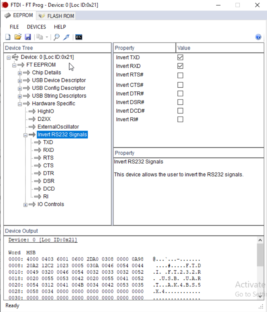
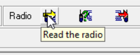
Using FT_PROG, scan for devices to load your FTDI board and open up "Invert RS232 Signals". Select "Invert TXD" and "Invert RXD" then hit the lightning bolt to program the device. Once programmed, reload the device with FT_PROG to verify the setting were persisted. This only works with genuine FTDI boards. A counterfeit eBay board will be able to be read by FT_PROG, but cannot be flashed.
3.3V must be used on the FTDI board. Also, be sure to use the digital ground.
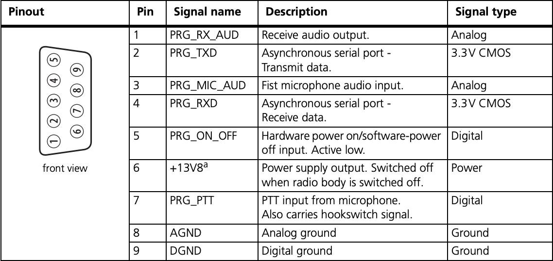
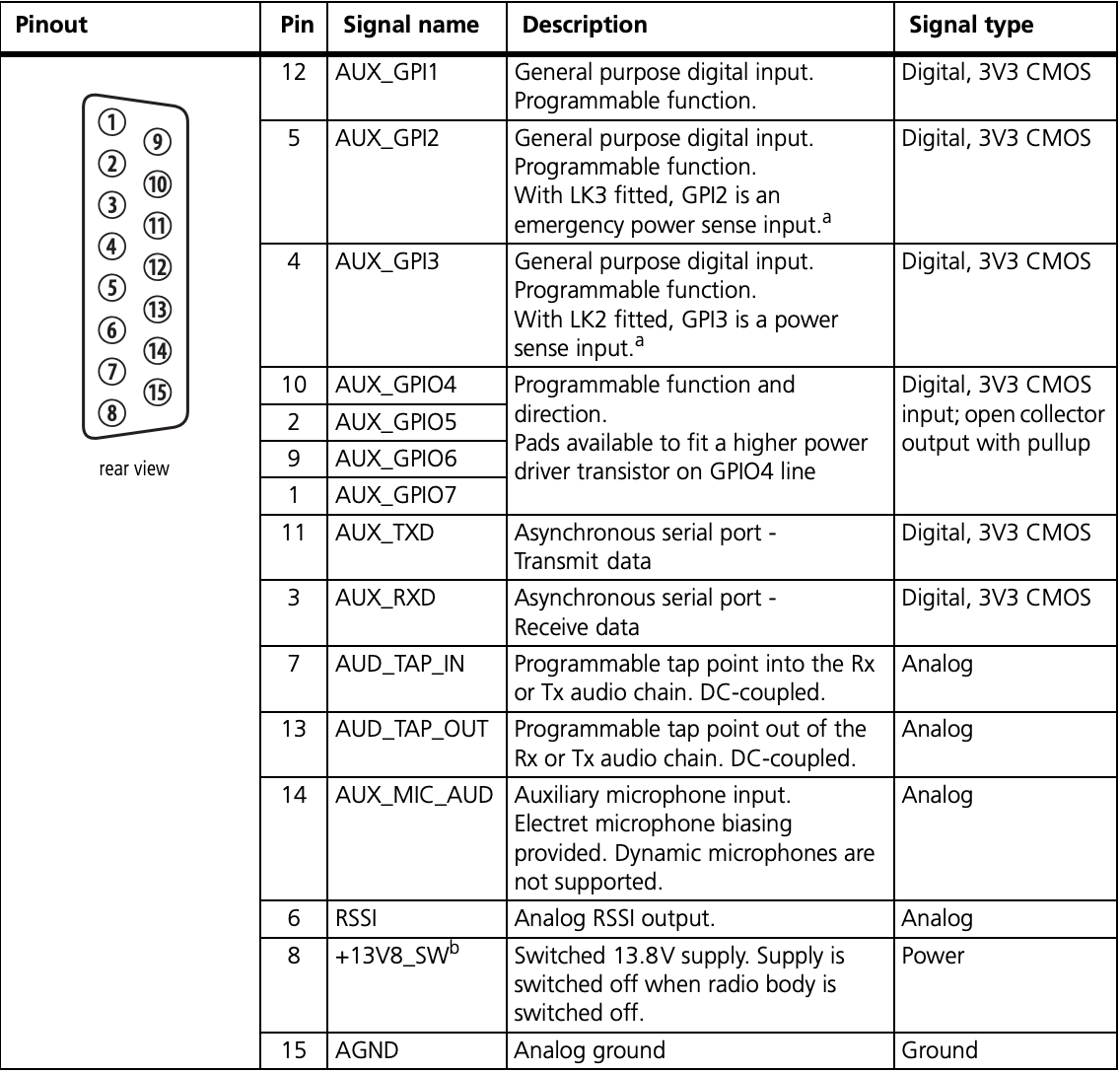
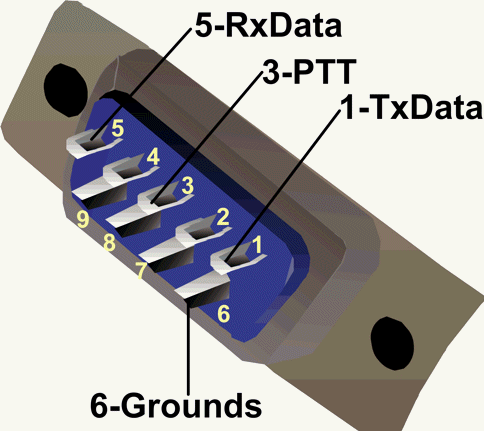
Programming is done via the front DE9 Male connector.
If your radio has a RJ-45 microphone connector, this adaptor will help: