Notes so I don't lose them!
RARS doc K5OE-handi.pdf
DF8GH handitenna
Antennas
From the radio to the sky and eventually to the other radio, the antenna system permits your transmitted signal to go from wired electrical energy to an electromagnetic wavefront which is converted back to electrical energy at the receiving antenna.
The antenna system on each end serves both as a converter of your radio's output into radiated electrical energy, and it also receives the other station's signal, which is hopefully loud enough to be decoded back into information by your receiver, and is also loud enough to overcome other noise on the frequency you are listening to.
A primer on antennas
First some mathematics.
No, I won't bring back the nightmares some of us had in school with the use of the word LO#######ITHM. Scary stuff there.
But I have to get pretty close to that.
There is a term:
decibel.
We use this to describe a relationship between two different signal levels.
It is also used to describe gain and loss for antennas, feedline, amplifiers, attenuators.
It is written as
dB, or
dBi, or
dBd, or
dBm, though each symbol has a different meaning.
The common element with this, at least when discussing RF signals and RF outputs, is that a
3dB change means
twice the power or signal, and a
10dB change means
10 times the power or signal.
Similarly
-10dB means
one tenth the power or signal, and
+30dB means
1000 times as much signal.
dB is used to discuss relative changes.
dBm, or
decibels-milliwatts, is used to discuss the absolute power output or sensitivity of a radio.
It refers to an absolute signal level.
dBi, or
decibels compared to isotropic is a measurment of the gain or loss of an antenna system, relative to a 0-gain isotropic theoretical spherical radiator.
dBd, or
decibels compared to a dipole, is like dBi but is offset by 2.15dB.
An antenna with
10dBd performance, is also
12.15dBi performance.
Receivers and Transmitters
Transmitter power is usually measured in watts of output.
Ham radio operators get used to figures in milliwatts, watts, and kilowatts.
A kilowatt is 60dB greater than a milliwatt.
Does that make sense?
Transmitter power and receive sensitivity can also be measured in dBm.
A transmitter, delivering 1mW of power, is measured in dBm as delivering 0dBm of output.
1 Watt of power is +30dBm.
A kilowatt is described as +60dBm.
A good receiver has a squelch break (i.e. the squelch opens enabling signal to be heard) at about -125dBm, and a full quieting FM signal is heard at about -105dBm.
For those following at home, -105dBm is about 31,000,000,000,000 times less signal than a 1 watt transmitter!
Now you know why we measure things in dB!
The signal that comes out of even a very low power transmitter is easily capable of damaging a receiver, if the transmitter coax is plugged directly into the receiver.
But if the antennas are sitting right next to each other, the receiver should survive it.
That's because the coupling of an antenna to the air, i.e. the radio waves leap from the wire to push electromagnetic waves into a relatively non-conductive air, and then back to another antenna, loses a huge amount of power.
Think in terms of -60dB, i.e. losing 999,999 out of a million parts of the signal.
What that means is if your receiver is only sensitive to -30dBm, it won't hear the 1 watt transmitter even sitting right next to it.
The good news is that receivers are usually a lot better than that.
Receiver Sensitivity
A receiver will have a sensitivity-level which defines how much radio frequency energy has to come from the antenna in order to get good intelligence from the signal.
More energy makes the intelligence more useful.
With FM, frequency modulation, the received message will acheive
full quieting when it is about 20dB stronger than the receiver sensitivity-level.
Full quieting means there is no radio-reception-caused background noise.
If an FM signal is at full quieting, then making the signal even stronger doesn't improve the quality of the intelligence being received.
With packet radio signals, we need signal which is close to full quieting (i.e. no background hiss) to receive the incoming message.
Along with overcoming interference from local sources, exceeding the sensitivity-level of the radio by 20dB or more must be acheived by the amount of energy in the signal arriving at the receiver in order for packet radio data to be perfectly decoded.
((Note! These figures need to be checked and may not apply to all radios))
Feedline
The feedline is responsible for transfering energy between the radio and the antenna.
Feedline is of two common classes, shielded unbalanced, and unshielded balanced.
There is also shielded balanced feedline, and other combinations, but for the most part, VHF and UHF transceivers emit and expect a shielded unbalanced feedline called coaxial cable.
Coaxial means that there are multiple conductors sharing an axis. This means there is a center wire, and then a surrounding wire.
In coax cable, the surrounding wire is called the shield and it is made of a braid of wire, or a solid copper or aluminum wrap.
The solid wrap is like a pipe but usually much thinner.
Most quality coax has a braid of wire surrounding (and electrically shorted to) a solid, but thin, aluminum pipe.
One of the properties of Radio Frequency physics is that RF energy conducts along the surface of a wire.
A shield has interesting effects here.
The inside surface of the shield participates as a conductor of radio frequency energy.
The shield may be connected directly to an Earth ground, house-ground, or the chassis of your DC powered radio.
The outside surface of the shield is supposed to be at ground potential and to have no RF energy.
The
center conductor of the coaxial cable is modulated with alternating current at the Radio Frequency of the radio receiver and transmitter.
This signal is, in turn, modulated with the intelligence you are attempting to transmit or receive.
The inside surface of the shield and the center conductor are both critical to delivering energy to and from the antenna.
Here is where things get weird.
The shield of the coax, notionally keeps the energy inside the coax and away from the outside environment, until the energy is delivered at the end of the coax.
The outside of the shield of the coax remains at ground potential and is not supposed to have any RF creeping around on the outside.
If energy
is transported on the outside of the coax, the energy is called
common mode current and is usually destructive because this brings radio energy from other equipment, to the receiver, and energy from your transmitter to other equipment.
Feedline characteristics and loss
Coax cable is designed to a specific impedance by specifying the thickness of the center conductor, and spacing between the center conductor and the shield.
The impedance specifies what load resistance of antenna is most efficiently carried by the coax cable.
If the impedance is wrong, or the spacing is changed, then some of the energy we want at the other end will be converted into heat.
At the low power we're using for our transmitters, this heat is negligable, but it also means that some or much of the energy we desire to reach the antenna will be lost.
Coax cable has many characteristics including an expected loss per length, and the ability of the coax to maintain the specified impedance when the coax is bent.
Naturally the coax which has the least loss per length is also either the hardest to bend, or the most likely to suffer additional loss when bent.
In addition, coax which has low loss can be damaged by bending.
The center conductor of coax is usually copper. However, the copper may be solid or stranded.
This matters because coax with a solid copper center conductor is less flexible than coax with a stranded copper center conductor.
If you bend coax with a solid copper center conductor too sharply, it may break.
A broken center conductor is invisible but renders the coax useless.
A good rule of thumb is to not bend your low-loss cable more often than necessary, and don't drag it through tight corners as it will change the impedance of the coax, resulting in loss.
Coax loss calculators exist on
the Interwebs and can tell you how much of your energy is converted to heat per length.
Keep in mind that your receive signal is affected as much as your transmit signal.
Good coax for our applications would have on the order of 3dB loss per hundred feet on whatever frequency you are operating.
3dB means that half of your signal is turned into heat, so 100watts is reduced to 50watts at the other end of the coax.
LMR400 or equivalent has 2.7dB loss per 100ft at 440mhz and 1.5dB loss per 100ft at 145mhz.
RG8X has about 4dB loss per 100ft at 145mhz and 8dB loss per 100ft at 440mhz. 8dB will turn 100 watts into 15 watts.
common-mode current
A preventable cause of RFI into household electronics and the ham-shack equipment, is common-mode-current.
As mentioned above, Common-mode-current is the appearence of RF energy on the outside surface of a shielded coaxial feedline.
This energy is present when an antenna is either incorrectly balanced, or is missing the counterpoise portion of an unbalanced antenna.
Testing for common-mode currents
One characteristic of common mode current is that the antenna will appear to have a higher or lower SWR depending on how far down the coax (from the antenna) the transmitter is placed.
The lowest SWR point repeats at a ratio related to the wavelength of the transmitted signal.
You can measure the SWR at the radio and find it high, but if you insert a jumper and SWR meter, the SWR could read as OK.
A ham's method for determining of common-mode current is a factor in antenna performance is to key up the transmitter through an SWR meter, and then run your hand closed around the coax up and down a length of the coax.
If the SWR changes with your hand position, then there is a problem and it is likely to be common-mode current.
Balanced vs Unbalanced
The most trivial antennas are a dipole and a ground plane.
A ground plane antenna (see below) has an unbalanced feed where the radiator is fed from the center shielded wire of the coax and the ground radials are fed from the shield part of the coax.
If the counterpoise wires (the ground plane radials) are sufficient, very little energy will appear back down the coax, outside of the antenna/coax/radio system.
A dipole is a balanced antenna and is fed with a balanced feed.
Dipoles fed directly with coax will work but there is some loss at the feedpoint (not much) and there is a high propability of common mode current issues.
The proper way of feeding a dipole is with a balanced to unbalanced converter of some kind.
The most common for a simple dipole fed with coax is a device called a BAL-UN transformer, or BALUN for short.
Antenna Gain
The amount of energy translated from the radio to the sky is limited to something short of 100% of the energy produced by the radio and delivered by the feedline.
If the energy was evenly distributed in a sphere of radio signals heading out into the sky, the antenna is said to be
isotropic.
This theoretical radiation pattern is practically impossible but it serves as a reference for comparing an antenna whose radiation pattern is not spherical.
Since your goal is to get energy from your transmitter to a certain receiver, you aren't really interested in the total radiated energy, as much as the directed energy which serves your purpose.
An antenna is said to have gain if more energy heads in the direction of the receiver than would be indicated by an isotrophic pattern.
The gain figure on an antenna is often specified in terms of the relationship between the desired pattern and a theoretical isotropic pattern.
If an antenna is said to have 10dBi gain, that means the energy sent in the direction of the other station is 10dB more than would be delivered by an isotripic antenna.
FYI, even a $3 home-made ground plane has at least 2dBi.
As mentioned above, some antennas manufacturers measure antennas against an isotropic antenna, and others are measured against a dipole, which is 2.15dBi (approx) so if the figure says 5dBd, it has more gain than a 7dBi antenna.
Pattern
There exists an imaginary antenna with universal omni-directionality in all 3 dimensions.
It is called an
isotropic antenna and it was mentioned back when we were discussing decibels.
A real antenna has a pattern of radiation (and reception) so not all directions are equally well supported.
The pattern of radiation causes gain and loss in different 3 dimensional directions.
For instance, an antenna that has minimal radiation straight up and straight down can have gain to the horizon.
Because antennas radiate in 3 dimensions, a description of the pattern of radiation should be 3 dimensional.
Often, however, the pattern of the antenna in at least one dimension is completely circular, and uninteresting.
Consequently, antenna patterns of radiation are usually shown as a 2-demensional graph.
A dipole, when driven by a radio on the dipole's resonant frequency, has a radiation pattern like this:
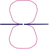 |
This image shows the pattern of a dipole from above. It's actually a donut running up and over and down and under the wire shown in blue.
Where the bulge-out is, there is RF radation. The further from the center of the drawing, the more radiation is implied.
A dipole, when operated at resonance, has very little radiation off the ends of the wire. |
 |
An omni directional vertical antenna will have a radiation patern of a circle around the antenna, if viewed from above.
But it will actually have an angle to the horizon which is described in a side view radiation pattern.
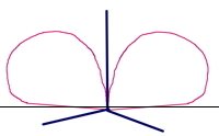 |
This image shows an example of what one omnidirectional vertical antenna might like from the side.
This antenna is not driving exactly to the horizon.
It has better signals going up into the sky!
Note that most side-looking radiation patterns have a center-divider identifying where the horizon is. |
|
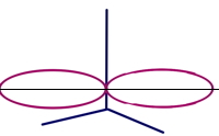 |
This radiation pattern shows a much more desirable omnidirectional vertical antenna! |
|
A professionally drawn antenna radiation pattern should show gradiations in dB to give absolute meaning to the pattern.
Do a web search for antenna radiation pattern and check out what you find.
Omni-directional Antenna
Antennas are always directional.
Even an omnidirectional antenna will favor the horizon over straight up and straight down.
The rejection of straight up and straight down is natural for an antenna with gain to the horizon.
The energy radiated by an antenna cannot be more than what reaches its feedpoint.
All we can do is direct that energy towards the desired direction.
An antenna is expected to be symetrical with respect to receive directionality and transmit directionality.
Negative Gain Antenna for noise elimination
Some antennas that have no gain, or that are even lossy at your chosen frequency, may still be worth consideration.
Consider the scenario where there is a noise source nearby spoiling your receiver's sensitivity.
Even with nobody talking on the frequency, the noise level is S9.
Exploration with portable equipment shows that the problem is a factory just behind your house.
Creating an antenna that is less sensitive to the noise source may turn a bad location into a usable location.
If you build a directional antenna that nulls out the noise source, you can now hear stations in other directions.
The antenna you might create for this purpose may be completely useless in transmit.
In that case, use a switch or relay to choose receive antenna vs transmit antenna?
This may seem like a desparate move, but cost-wise it isn't so crazy compared to selling your house and moving.
There is a receive-only antenna called a beverage that is decent gain in a single direction, but is large enough that it can only rotate (it always rotates) once a day (and takes 24 hours to do it).
Polarization
Radio signals can be polarized.
The impact of this is that it is possible to have an antenna of one polarizaton which transmits a signal that will impact a second, otherwise polarized antenna, with much less energy than if the two antennas were the same polarization.
Ham radio antennas are often polarized.
Mobile antennas are usually vertically polarized, becuase vertically polarized antennas are easier to mount on a car.
Base station antennas for ham radio are always polarized, but selecting which polarization is up to the ham.
Many antenna designs work vertical or horizontal, but during purchase, construction, or installation, a choice must be made.
The optimal selection for polarization depends on many factors including what the desired or common polarization is for the stations being worked.
Most store-bought antennas cannot be mounted other than their design polarization, or are at least impractical to mount in the other polarization.
There are four common polarizations.
These are vertical, horizontal, circular-left and circular-right.
Vertical is commonly used in FM, mostly because FM's primary market is mobile to base, or mobile to mobile, and vertical mobile antennas are easier to acquire, build and install than horizontal mobile antennas.
Horizontal is commonly used in short-wave SSB operation because horizonal antennas are easier to mount for fixed station use and there may be some performance advantages in terms of solar noise at short wave frequencies. .
Circular polarization is commonly used in satellite operation, because the satellites, being up, wouldn't have a specific polarization common to all operators.
Circular has some attributes which are friendly to the operators. Read on...
Attributes of Polarization
Directionality -- horizontal yagis have poor front to back ratio but excellent rejection to the side.
Vertical yagis have excellent front to back ratio but poor rejection to the side.
... more details and photos required here! ...
Polarization for packet radio purposes
Horizontal yagis, because they reject to the side, are better for high multi-path environments, like when there are water towers around the stations or in the path between the stations.
... more details and photos required here! ...
Connectors
Feedline connectors have been in common use since World War 2.
Prior to feedline connectors, the antenna wires were connected using thumb-screws or banana plugs.
The UHF connector, called PL259, SO239, were introduced to support coaxial feedline in a time when operation above 300Mhz with low power and weak signals was not a consideration.
Compared to modern Radio Frequency electronics, the sensitivity of receivers in those days was pretty terrible.
My point is, the decisions in selection and naming of standard connectors made in 1940 should not be taken as seriously as we might take some of the other standards created in that time period.
The connectors I find most common in my hamshack are:
UHF, N, TNC, BNC, SMA, mini-UHF.
Each of these has benefits and each has limitations.
There are also ease-of-use considerations, both from the connection and disconnection of the connectors, and from the ease of assembly of cables and design, construction, and maintenance of equipment using each type of connector.
... more details and photos required here! ...
noise
mounting
Interference From Ham Transmissions
One of the impacts of running a transmitter is that radio wave energy will be presented.
Interference from the radio transmisison is called RFI.
Interfence is described as some behavior in equipment other than the transmitter which is undesirable.
RFI caused by our packet radio system sometimes causes buzzing in audio systems, bad behavior in the digital components of the packet station, and reduction of sensitivity of receivers in the packet station.
The interference to the other receivers is particularly important in a packet station having more than one transceiver.
What kind of antenna should you get?
What antennas you use depends largely on the mounting positions available at your station.
I can think of several broad categories of antenna sites.
- Tower and mast mounting with vertical space available
- Mast mounting or roof mounting with only one short pipe
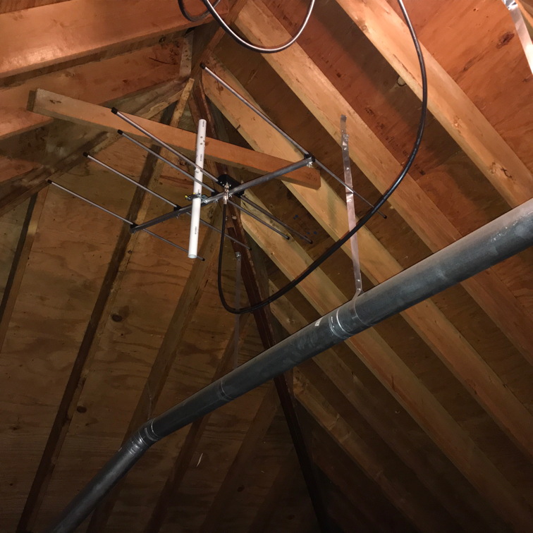
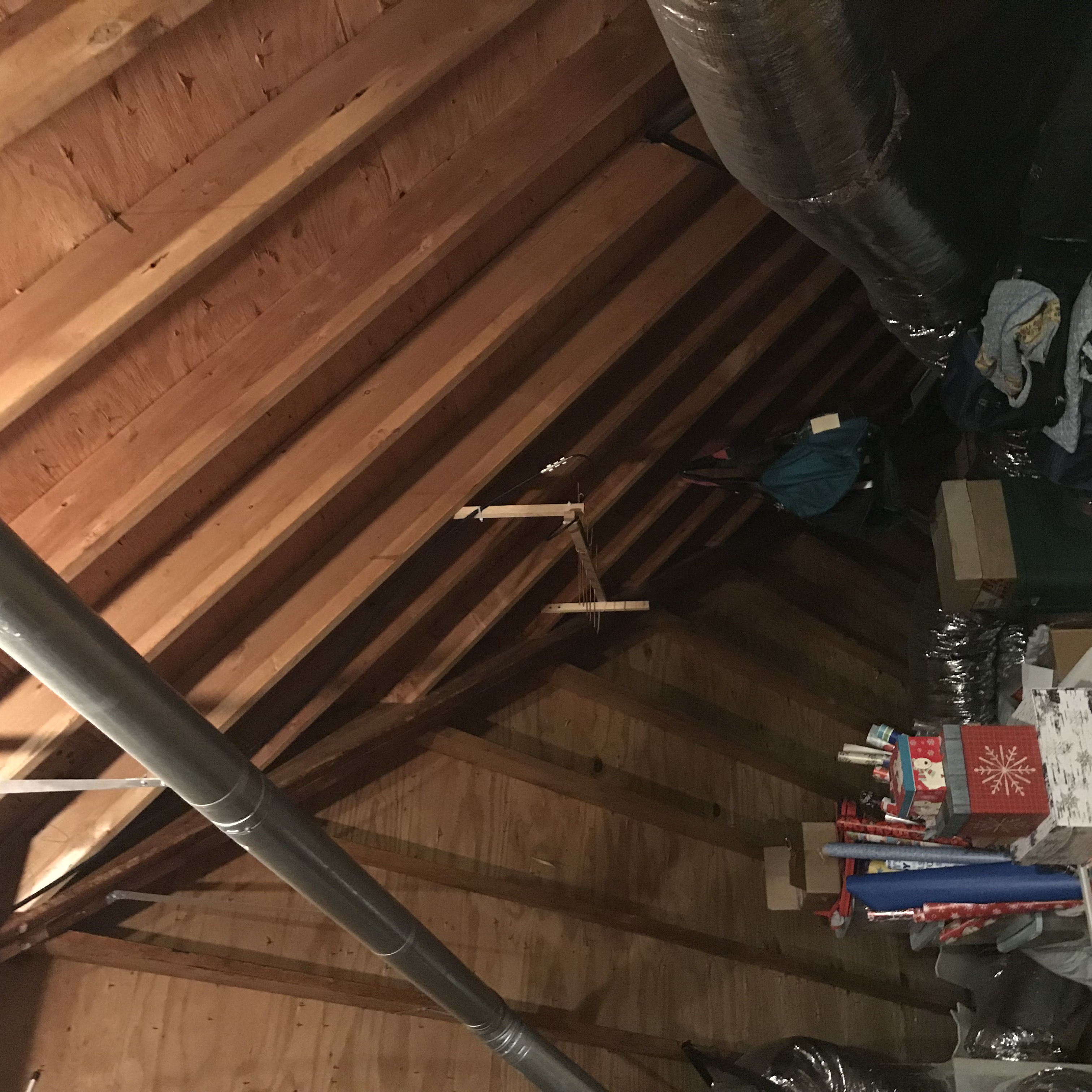
- Attic installations
- Antenna hanging from Tree
- Wire antenna between trees or buildings or masts
- Antenna mounted to side-arm on tree
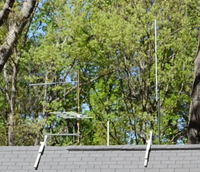
Tower and masts may afford a top mounted omnidirectional vertical as well as end-mount yagis, or even room for a 6meter horizontal yagi.
Attics can afford multiple high frequency yagis.
Attics are best for high frequencies however because in-house noise tends to make 6meters deaf and sometimes even 2meters is impacted.
Roof mounts with room for only one omnidirectional vertical can still have multiple radio links by using a multi-band antennas.
Tree mounted antennas can be positioned in several ways, hung from a rope, top-of-tree placement, side-arm placement.
Side-arms are great for short yagis and omnis designed to be mast or tower mounted.
Rope hung antennas must usually be omnidirectional verticals, though with a little ingenuity a yagi may also be suspended.
Really cheap antennas
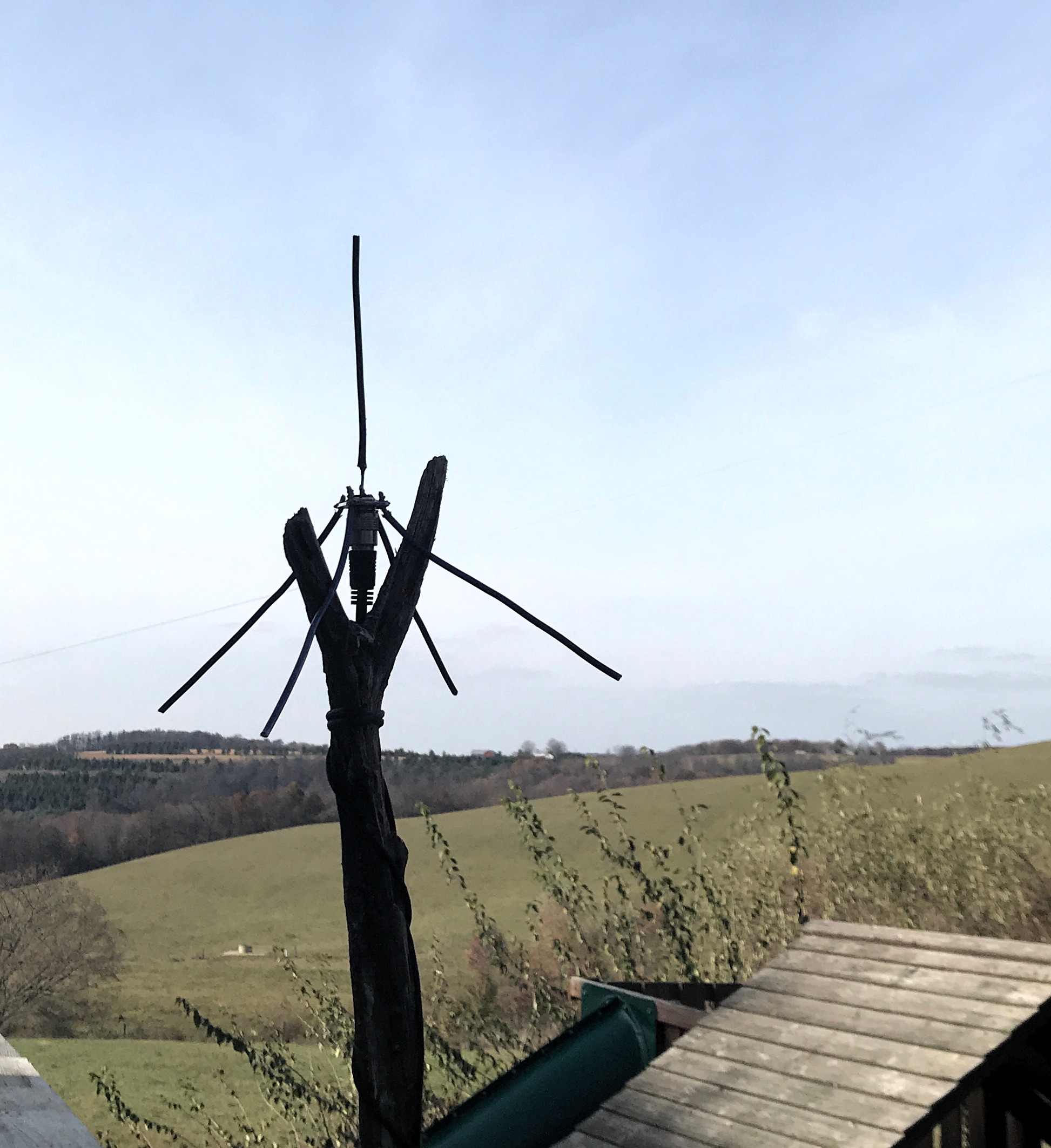
Ground Plane
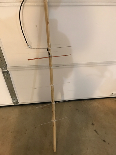
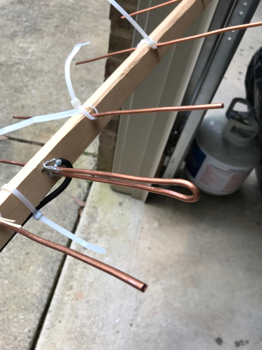
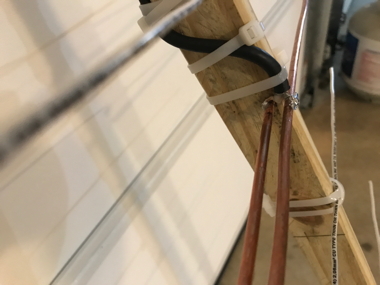
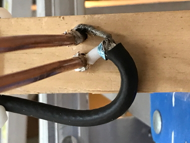
For packet stations where line of site is assured or very short distances are involved, (a mile or two?), consider home-brewing a quarter wave ground-plane or building a WA5VJB yagi out of copper wire and wood.
 |
This 446Mhz antenna is about a foot tall for 446mhz and cost about $6 in parts, not counting the coax cable.
The parts cost more than that but yielded half a dozen antennas.
There is no problem hanging this from a tree.
On 2m and 6m the materials for the ground plane might need to be stiffer than what you can get away with for 440.
This antenna was constructed using 10AWG solid ground wire ($22 for 50 feet on Amazon) and a SO239 chassis connector.
KC3IBN is using this antenna for a 1.5 mile TARPN point to point link near Danville, PA.
The other end of the link is a Comet GP-15 tri-band vertical whose 6m side is also a packet link.
|
Article about 1/4 wave ground planes is here:
SO-238-Ant
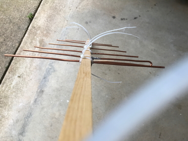
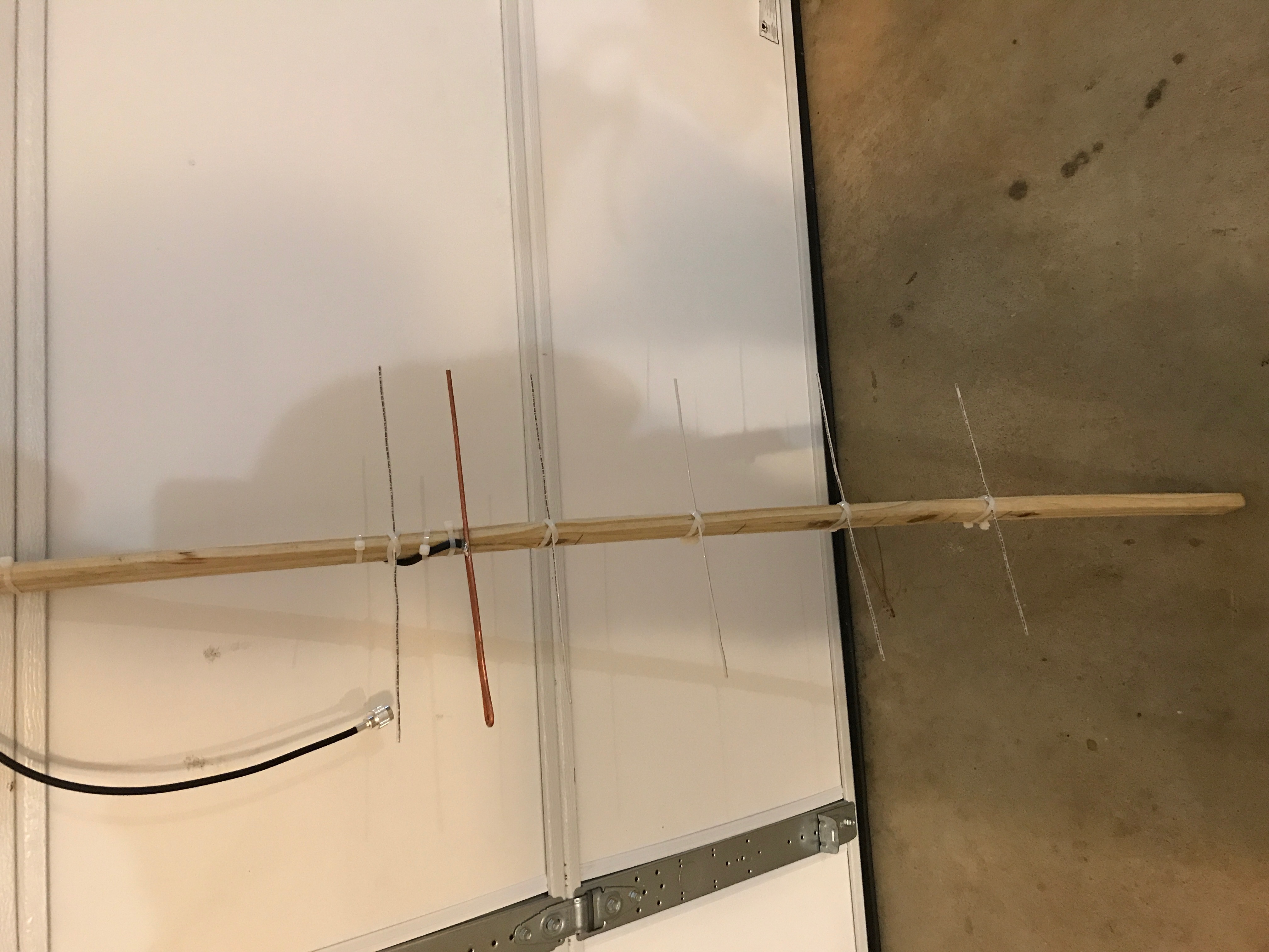
WA5VJB Cheap Yagi
Building your own yagi isn't all that hard.
The big disadvantage of this antenna over the commercial varients is weather worthiness, and maybe hassle-factor.
But if you are doing an indoor antenna, this yagi has the advantage that you can cut it for the frequency you want.
Commercial UHF ham yagis are available for 430 to 435mhz, and for 440 to 450.
Nothing serves the 420 to 430 range and we can get radios to run there.
So building one's own antenna is possibly the way to go.
cheap yagi antennas for 2m, 220, 440.

See also
WA5VJB CheapYagi PDF for another article on the same antenna.
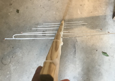
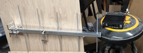
Based on WA5VJB's design, N3LTV and I worked out a spreadsheet (Excel 2009 or later) to modify the numbers so we could pick a 420-450 center frequency for the antenna.
Download the spreadsheet from here.
Photos of N3LTV's antennas
Two different antennas are represented, both built with the same instructions.
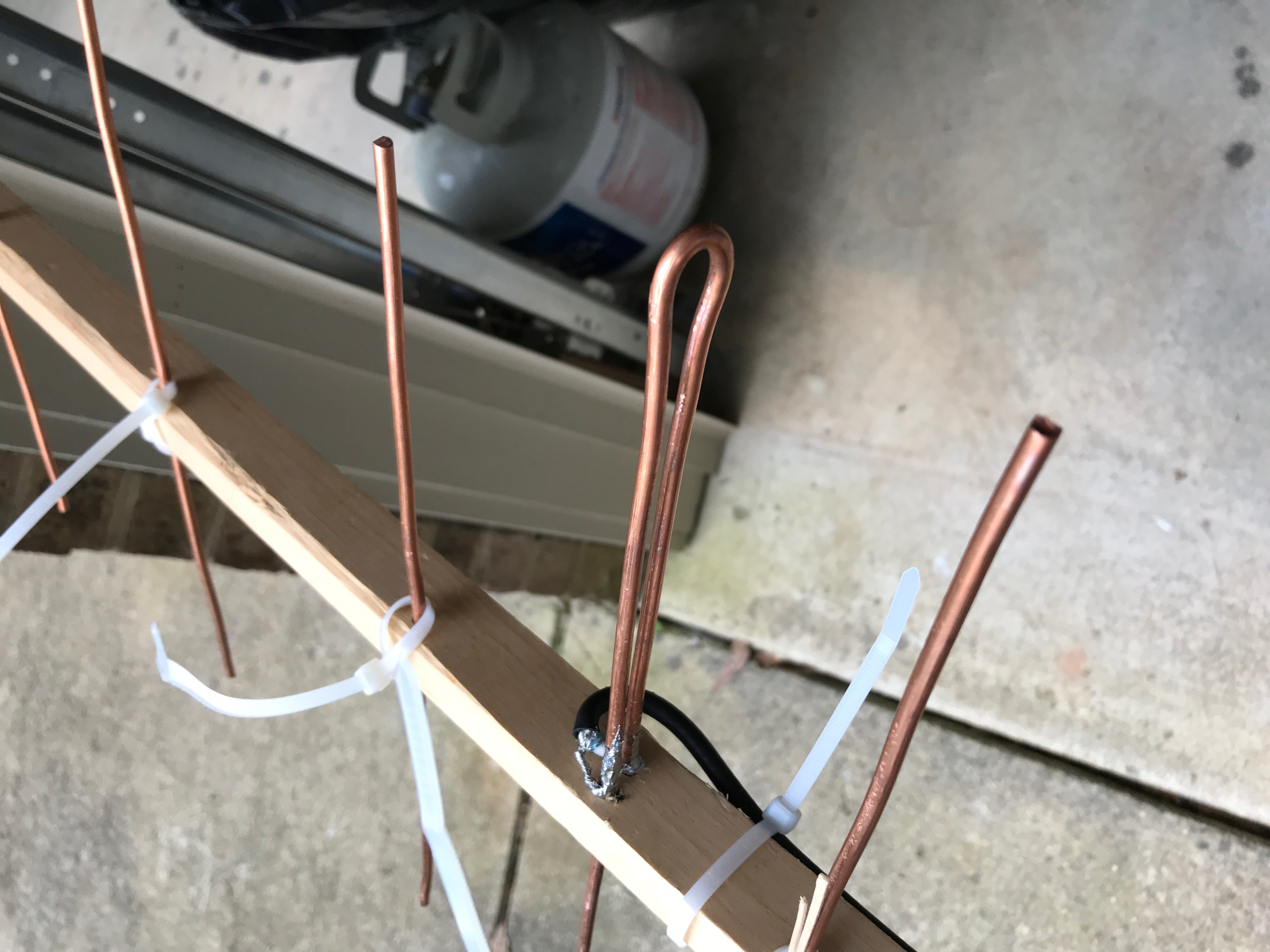
The only caveat is that the unit with the thinner copper wire (insulated) didn't tune up properly until the driven element was replaced with the recommended 10-gauge copper.
It appears that the parasitic reflector and director elements can be thinner wire, but the driven element needs to use the 10gauge wire.
Click to enlarge each photo to a new browser tab


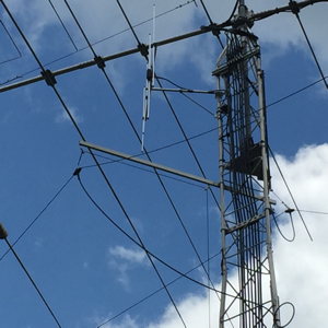
Masts and Mounting Structures
Tree mounting is discussed later in this page.
|
Mast mounting is very common in our NCPACKET group.
One method is to use a 2" inside diameter or greater schedule 40 (really heavy steel) pipe of 20' length or so and then bolt a 10 foot 1+1/4" EMT Conduit on the inside, top, of the pipe.
There are several pipe suppliers in the region.
The nice thing about this arrangement is that it gets you above the roof of your house or out-building without climbing and provides mounting for VHF yagis and a vertical.
It may also be used free-standing with three guy ropes tied to heavy trees (use eye bolts at the 6' level of 40 year old trees, for instance).
Expected costs for the assembly are about $75 for a 28' tall mast.
The example shown to the right used a 5' TV mast in the top of a 20' tall 2" I.D. steel pipe.
This is the AARONJ node and supports an 11 element 433Mhz horizontal yagi and a 2 element 50.99mhz MOXON yagi.
|
Click to Embiggen
|
Another solution is to use a push-up mast.
This company sells push-up masts up to 38' high for $150: 3 Star Inc.
A push-up mast is shipped with several pipes inside each other with a guy-wire/guy-rope attachment point at the top of each of the pipes.
The top of each pipe also provides a tightening ring for the pipe mounted inside.
The user would stand on a step-ladder and push up the thinnest pipe to its maximum extension, then tighten the ring for that pipe.
Next the 2nd thinnest pipe is pushed up to its maximum extension and its hardware is tightened.
Some of these masts have five pipes inside each other.
This provides up to 38' of mast, shipped in a single box of about 10' long.
Yagis
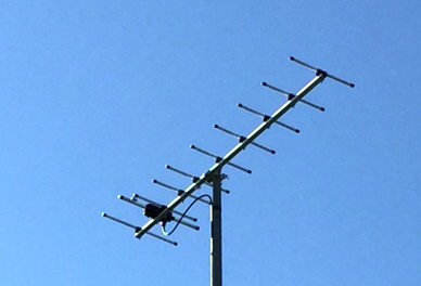
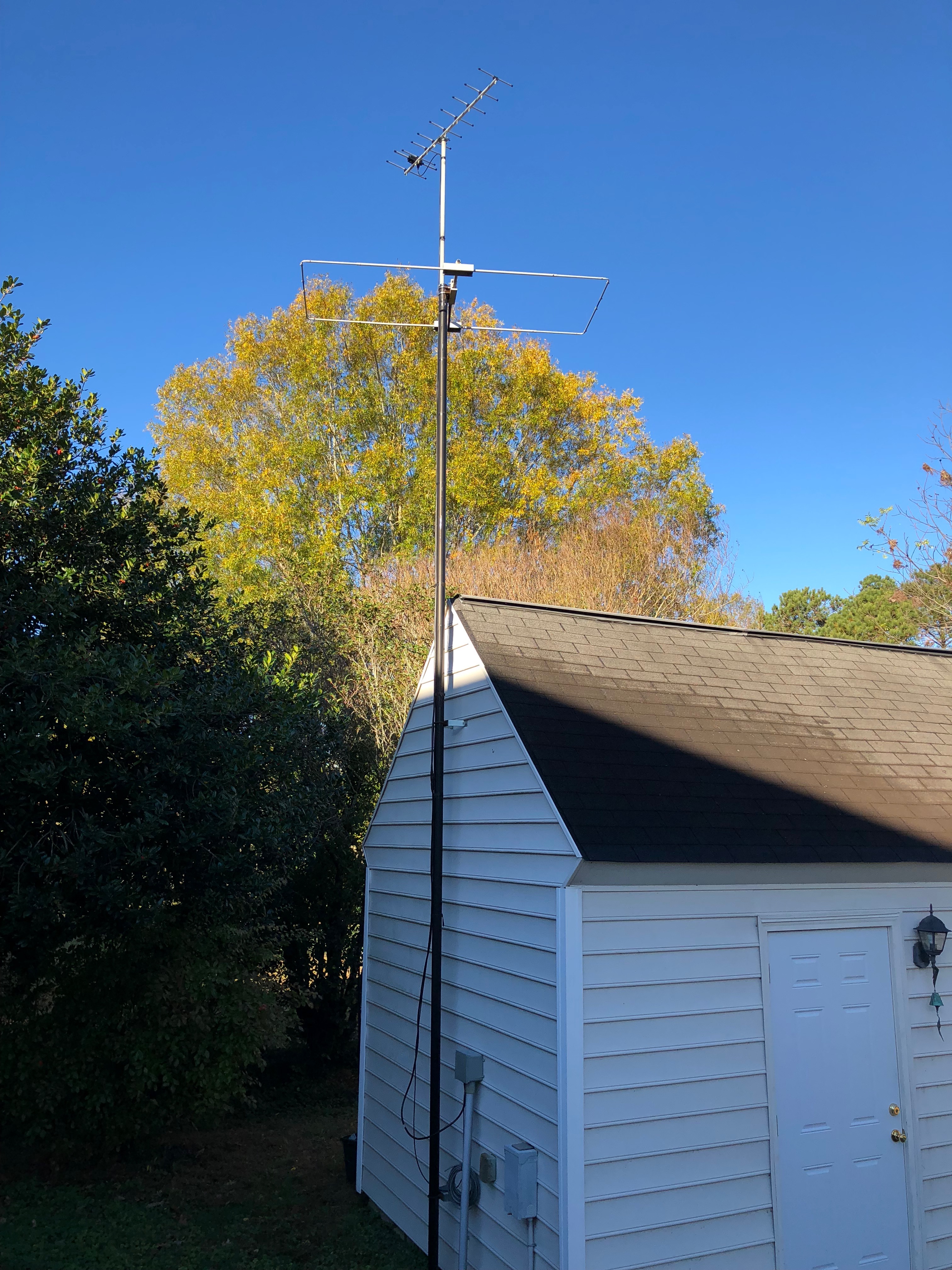
- 50Mhz -- PAR-Electronics makes a very light, highly functional Moxon yagi.
- 144-148Mhz -- The Hygain VB-25FM 6'3" long, 2.9lbs
- 222Mhz -- Arrow Antennas 220-5s -- end mount 5 element yagi
- 420-450Mhz -- Ailunce HD1 3 or 5 element end-mount yagi
Arrow solid-element yagi
- 433Mhz -- Diamond A430s10 -- Very nice 10 element horizontal 433Mhz antenna. Don't use on 440 and up, however.
Beware that 6m and 2m antennas will bring in electrical noise if mounted too close to a modern residence.
Hy-Gain end-mount 5 element vertical 2m yagi, VB-25FM.
Gigaparts has the VB-25FM for about $135 (They were $55 when we started this project!)
The left photo is from the TADD node. The right is from the FIN node.
Ailunce makes $30 and $40 end-mount UHF yagis for 420 to 450mhz.
They require tuning of the gamma match after assembly but they are pretty easy to manage.
The 3-element antenna can be bought
on eBay for about $30 including shipping.
The 5-element antenna can be bought
on eBay for about $40 including shipping.
Both have been shown to work well.
Arrow Antennas makes and sells a decent end-mount yagi for 220, and for 440Mhz.
They also have a center mount (horizontal) 2m yagi and 6m yagi.
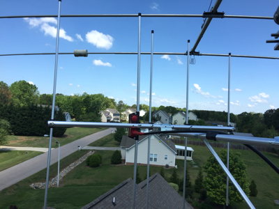
Here, from the TADD node, are the 220-5s 220Mhz antenna, mounted horizontal in this case, and below it is the 440-5s 440Mhz Arrow antenna, mounted vertical.
More TADD node pix.
Click on the image to see a few more images and descriptions.
Antennas shown are:
- Hygain VB-25FM 2m yagi,
- Arrow 220-5s 220Mhz yagi,
- Arrow 440-5s 440 yagi, and
- MFJ 1532 tri-band vertical.
The white pole in the middle was the mount for an experimental antenna, now removed.
|
|
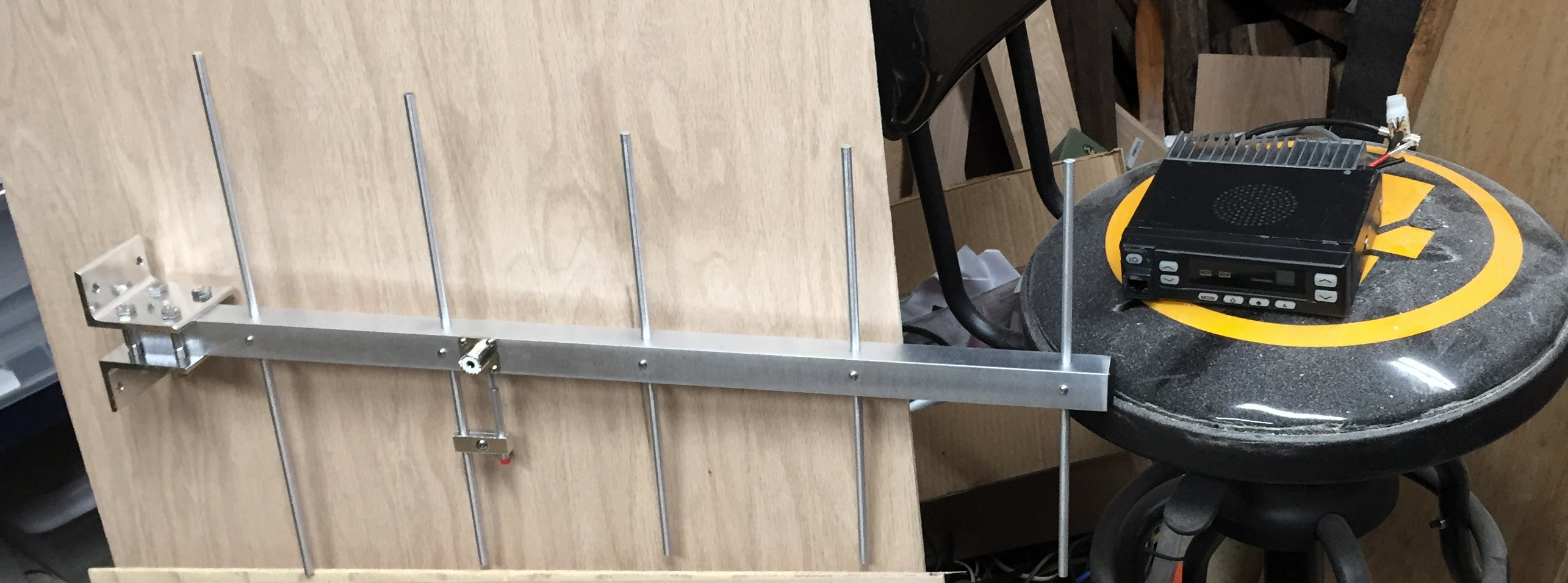
Fin NC4FG's Arrow 440-5s antenna shown with a Kenwood UHF mobile radio and bar stool for scale. .
 Gigaparts
 has very competitive prices.
If you have a rigid mount available, end-mount Yagis are much nicer than the multi-band omni antenna.
In some cases, height is better than gain, but gain sure is nice.
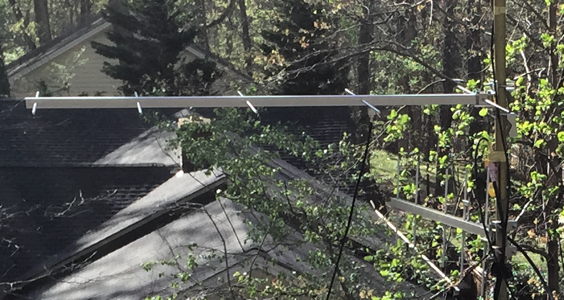
Diamond makes a pair of good working yagis, a144s5 and a430s10.
They cost about $55 each.
They are each equipped for horizontal mounting.
For vertical mounting you need a side mount bracket / side-arm.
Diamond sells this as an accessory for about $25 which I consider to be rather expensive!
The a430s10 is made for 432Mhz and is out of its useful frequency range in the 440 to 450 FM band.
It works great at 433 to 434Mhz.
There are 8 in the network as of November 2018 including CHRIS, FFVC, TADD, ADAM, VON, GREG, AARON and BILLY nodes.
The nice thing about having a link at 433Mhz is that it is easier to keep it from interfering with repeater operations or another link in the 440Mhz range.
The a144s5 seems to work quite well -- As of November 2018, six were in use, horizontally mounted, at TADD, TILL, DOUG, and GREG nodes.
The Diamond beams may be assembled in about 2 minutes without tools.
If you have a link which can use a yagi on each end and can be supported by 433Mhz radios, this may be the way to go.
One notable feature is that the antenna tuning is fixed.
It takes no time at all to tune it, because you can't.
The A430s10 is good for the 433.1 to 433.9 Mhz frequency range supported by TK805d and Maxon SD125 plus many other commercial surplus radios.
|
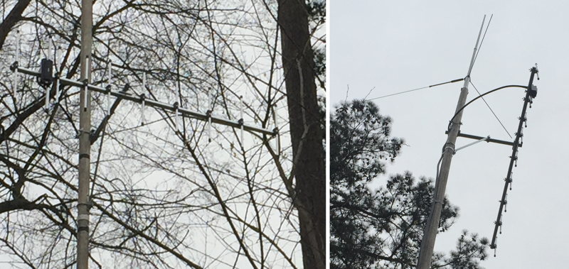
Diamond A430s10 mounted horizontal at AARON node
|
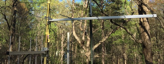
Here is the Diamond A430s10 mounted below a GP15 at the SKIP node. The A430s10 is shown in vertical mode with the KB430 side-arm accessory:
Here is the Diamond A144s5 mounted below several HF and VHF antennas at the DAVIS node.
The HF beam is not as close to the 2m yagi as it looks. The HF beam is very long.
The A144s5 is shown in vertical mode with the KB144 side-arm accessory:
Antennas In Trees
The local network has seen 3 different methods for placing antennas in trees. These are:
- Tree to tree dipoles
- Side-arm bolted into tree with mast and antenna
- Rope hung antennas
Tree to Tree dipoles are not generally very high gain but for 6m, where it is somewhat harder to get high gain, a dipole may be adequate.
Furthermore, trees can support a 6m dipole at a decently high elevation above ground.
The rope hung antenna is the easiest for achieving altitude and is somewhat subtle, an important feature when in an HOA community.
The side-arm gives great versatility and permits yagis to be mounted.
Tree to Tree dipole
Below is a photo of NC4FG's tree to tree 6m dipole hanging about 15 feet above his mast mounted yagis.
The technique for hanging a dipole usually involves sling-shots or other projectile throwing devices covered below.
The dipole is suspended from its ends by ropes.
One rope goes to one tree and is tied down.
The other rope goes through a pully on a second tree and then drops to a weight which holds the dipole mostly straight.
The reason for the pulley and the weight is that the two trees will move independently and you don't want your dipole ripped in half.
The cost of a tree to tree 6m dipole is about $35 for a
W2DU-VHF balun, about $5 for wire, $3 for two insulators, $10 for a pulley, $4 for two eye hooks, $20 for 150' of rope?, and about $50 for RG8X coax.
Side Arm Antenna
Don't get killed.
I'm not an expert in tree health.
If the antenna is omnidirectional, the side arm has to put the antenna a large fraction of a wavelength away from the tree.
For 6meters you'd want the antenna about 12 feet from the tree.
If the antenna is a yagi, you can aim the yagi directly away from the tree in which case the reflector could be almost against the bark.
If the antenna is aiming across the tree, then you again want to space it out a large fraction of a wavelength from the tree.
For 440Mhz, 70centimeters, you could have it 2 feet from the tree and the antenna would be nearly perfect.
In this photo, KE4VNC, has the antenna about 18 inches from the tree and the antenna worked as desired.
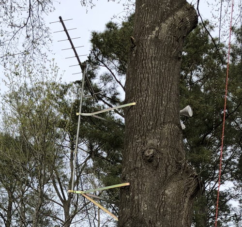
The mount Billy is using is a
Rohn WN24d which costs about $70.
Another source for $38 delivered is
SolidSignal.com EZ-30-24 24-inch mount
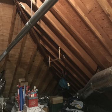
Antenna in the Attic
Antennas can be installed in the attic.
This is not ideal for several reasons: Household noise at 2m and 6m make those bands hard to use. Metal wire, ducting and other equipment in the attic will affect antenna performance.
However, sometimes it's all you are going to get.
-
The RF noise on 6m and the sensitivity of household electronics to 6m (stereos, clock radios, alarm systems) make operating 6m at greater than 5 watts almost impossible.
- 2m is much better in that at least household electronics isn't laid waste by your transmissions.
But the noise level on 2m receive make it unable to hear other than really strong signals.
- 220Mhz is better but more expensive because there are few commercial surplus radio deals to be had but if you have the gear, 220 is a good compromise between the range of 2m and quiet house for attic antenna.
- 440Mhz is ok in the attic if the antenna can be placed ok and if your linking neighbor is close enough.
- 900Mhz is even better still but the range is really short unless you have real line of sight.
In the trees we have gotten about a mile with 20 watts on 900Mhz.
-
Note that at the higher frequencies the absorption of RF by building materials gets worse.
The range of an outside antenna will be better.
| |
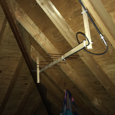
Notes on installing horizontal yagis in an attic
- Look for horizontal pieces of metal that are within 6' of a horizontal antenna.
Vertical pieces aren't that much of a problem to a horizontal antenna
- Any metal that is 30" or longer that is within 6' of a 2m antenna is worrisome,
but horizontal 1/4 wave pieces of metal are likely to be a problem (19 inches or longer on 2m, 7 inches or longer on 440) for a horizontal antenna.
In a UHF 440 installation, the distances are much smaller since the wavelength is one third of 2m.
- There should be no furnaces or big ducts in the direction the antenna is aiming.
- Anything behind the antenna is ok. in front of or above or below or left or right is more of an issue.
- The coax feed should drop straight down from the feedpoint on a horizontal antenna. Not go horizontal at all.
On a vertical antenna the coax should go left or right from the antenna and then wrap around the back of the antenna.
- Coax should go straight away from the antenna for at least a half wave (or straight up for a half wave) but running the coax parallel to the boom is also ok, depending on where on the driven element the feed point is located.
Best is to go straight down or up as far as practical before curving it to run straight back to behind the antenna.
- Look for sharp bends or kinks in the coax.
The coax should be straight or gently bent.
Coax lengths of > 50 feet or so should only be done with LMR400 or better coax.
- Use N connectors for UHF 440 antennas.
- Make sure you get a compass alignment OUTSIDE the house, and figure out where the beam should be aimed relative to the house, then go inside and point it correctly.
The compass can be badly affected by metal and AC wiring inside the house so don't trust the compass while inside the house.
This includes cellphone devices!
Double check the angle used in the attic because almost everybody gets confused going into and out of the attic.
Note the image below. The coax is properly run down and out the back of the antenna.
My only complaint was that the metal duct was big and close enough that it could change the pattern.
Watch that any metal straps or wires going through the antenna are insulated.
Oddly enough, that strap holding the duct is not going to hurt the antenna pattern because it is perpendicular to both the elements and the boom, so long as it isn't metal on metal contact with the antenna, it shouldn't affect the pattern.
Doug is going to move the antenna to the left 9 inches or so which should make it better.
|
|
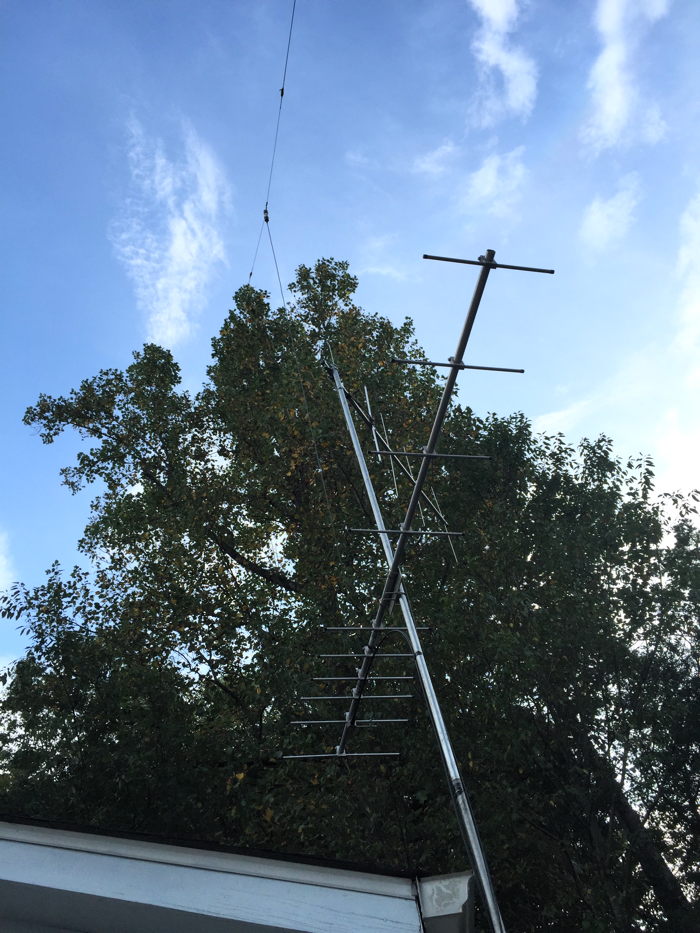
Rope Hung Antenna
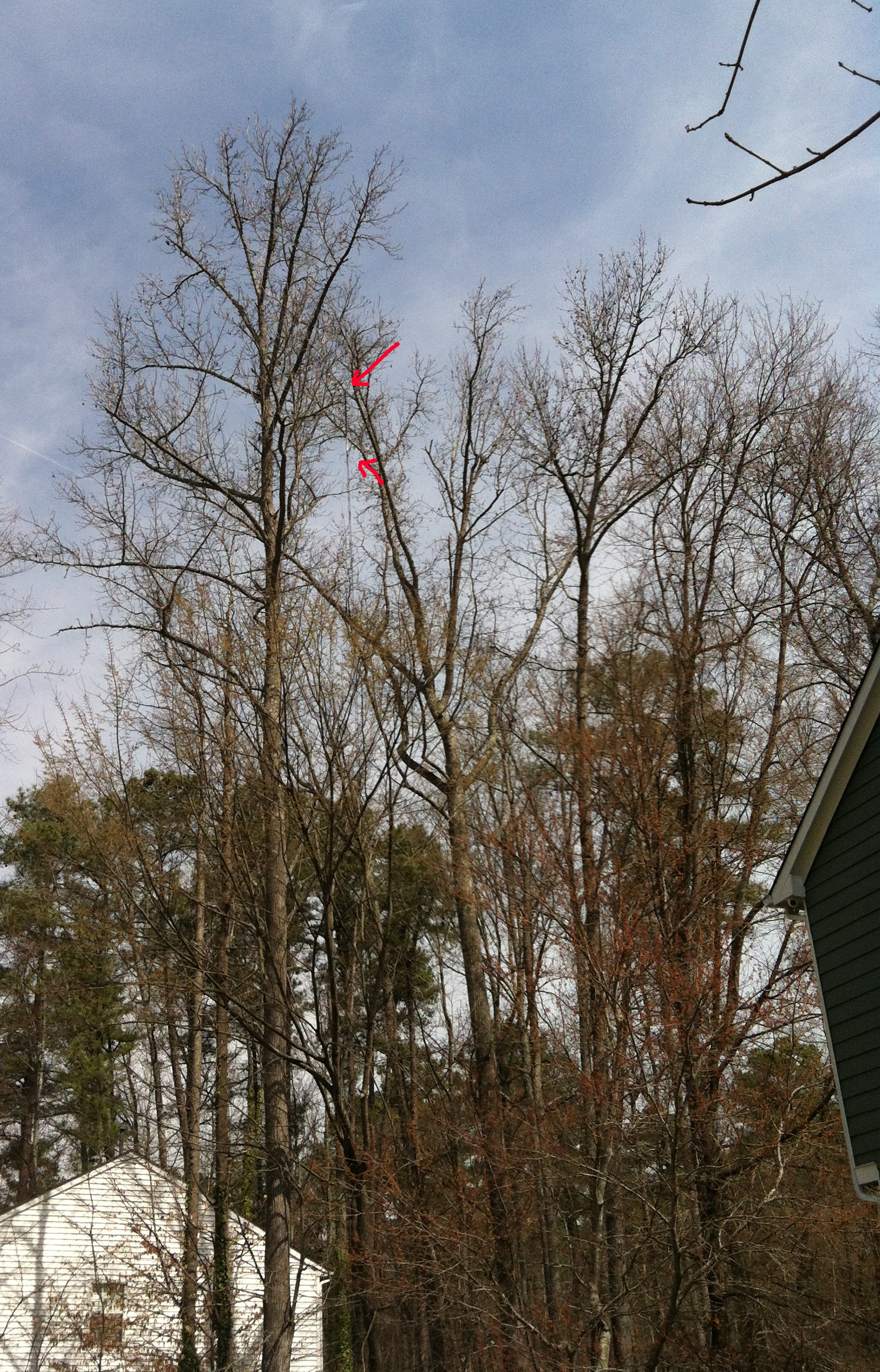
Hanging an antenna from a tree is a great thing, but you have to make sure the branches aren't right near the antenna or your antenna's performance will be compromised.
I used to like tri-band antennas for hanging but more recently I discovered how poor those antennas perform on the 3 bands, compared to a dual band antenna.
I've come to like the Comet GP-3, GP-6, Diamond X50 and X300 antennas.
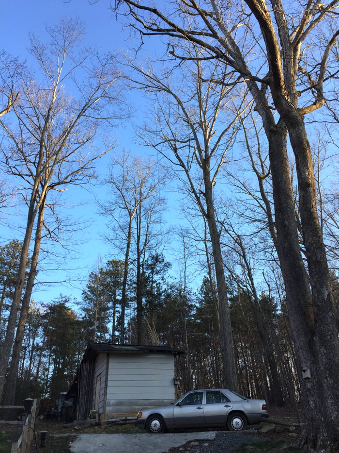
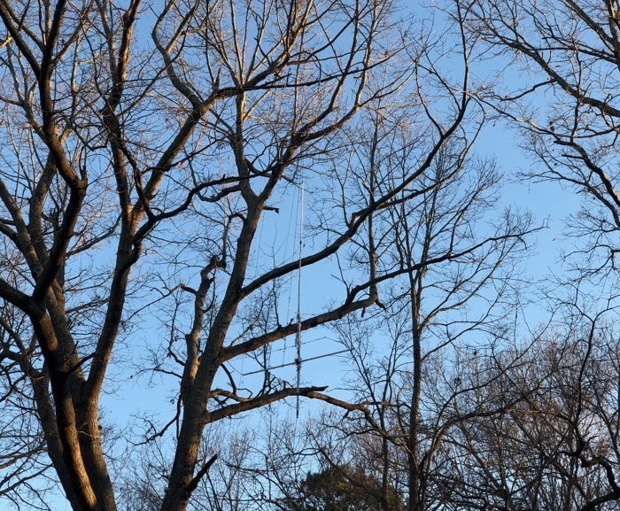
Below is a tree-hung GP-6 whose base is 85 feet off the ground.
Cost including 100' of JefaTech LL400 and 200' of rope was about $400.
$160 (antennna) $110 (coax) $6 (connectors) $50 (rope) $15 (pulley) $50 (diplexer)
The iphone lens perverted the scaling as the car looks taller than the antenna though the antenna is 10 feet tall.
This share-able document shows how to install a vertical omni antenna in a tree.
Click to Embiggen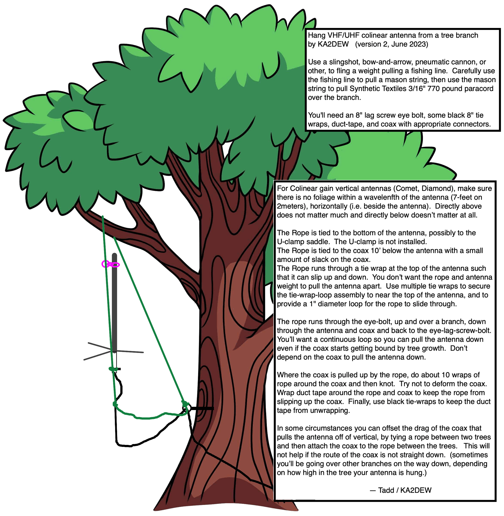
Hanging a yagi antenna
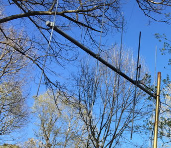
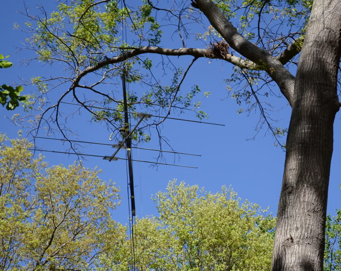
Below is a 3 element 6m yagi hanging from a tree.
This required a branch which was fairly heavy, fairly long, and was the first branch on that side of the tree.
The antenna, in this case, has 9' long elements and is about 6' boom-length.
There is an 8' aluminum mast onto which the antenna is mounted.
The mast is hung from the top and the coax is taped to the mast.
This forces the masting to be vertical.
The antenna, which is both balanced and light-weight, will then stay horizontal.
The direction of the antenna is controlled by a very lightweight string tied to one end of the boom and to a tree or other object away from the antenna, mostly horizontal.
The advantage of hanging the antenna from a tree, instead of placing it on a mast on the house, was that the noise level caused by electronics and LED incandescent replacement bulbs is much reduced by being located away from the house.
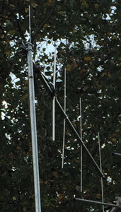
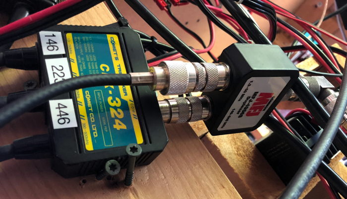
Below is a Comet CX-333 144/220/440 tri-band vertical mounted to a 6' mast with a PAR antennas 6-meter stressed MOXON antenna mounted below.
The MOXON is a 2 element beam directional antenna.
The two antennas are fed into an HF + VHF diplexer to combine the two antennas onto a single coax.
In the ham shack there is another HF + VHF diplexer. The VHF side is then fed into a tri-band 144/220/440 triplexer.
This single antenna system provides antennas for four different ham radios simultaneously and is fed with one run of coax.
The total cost of this system including 200' of JefaTech LL400, 200foot of Synthetic Textiles rope, and 3 used triplexers and diplexers from eBay was about $650.
The average of a new antenna system for a TARPN is closer to $90 per radio.
This one was $160 per radio but this one is away from household noise, is 20' higher than the house, and isn't visible to the casual observer.
The real flaw in this kind of system, compared to one mounted on a mast, is that the ropes and trees compete to wreck each other.
Between squirrels eating the ropes and tree bark growing over the ropes, this is higher in maintenance than something on a mast.
Expected life of this system is four years without major work.
Installing the rope-hung antenna
You need to have
- Hard hats,
- fishing line, (thickness depends on the shooting device) length 300 feet or so?
- casting reel,
- fishing weight (0.5oz to 2oz depending on the shooting device?)
- Mason Twine (Everbuilt #18x500 ft Nylon Mason Twine Home Depot #72956 @$13/spool),
- Ropes,
- Gloves to grip rope.
- 5" long 3/8" ScrewEye,
- person who can shoot the fishing line over a high branch,
- shooting device,
- 5lb barbell with handle,
- Black tape,
- a dozen or so black plastic 6" Tie wraps.
- Coax on roll, pipe to support the coax roll.
- Paracord to hold the antenna for several years. You'll need about 4x the height of the branch you'll hang on, though at the end of the day you'll only leave behind about 2x the height.
I like the Synthetic Textiles 3/16" 770 pound stuff myself.
Costs about $70 + shipping for 500 feet.
Sold in 1000 foot spools for $130 & free delivery from HRO.
Be careful with the cardboard spools as they have been known (yes, me) to disintegrate in wet grass.
I found that re-winding the paracord onto an excess coax spool is a very good idea.
The shooting device in this context could be a pneumatic cannon, like a potato gun or marshmallow gun, a slingshot, a bow-and-arrow, crossbow, or some other method for putting a fishing line over a 120 foot high tree.
Getting Started
This process involves physical manipulation of objects which have real weight and which if allowed to fall on an unprotected head or face could be hazardous.
Take appropriate precautions!
Especially be aware of falling branches.
First you need to put a fishing line over the tree or over the appropriate branch.
Use a slingshot or tennis ball cannon with a tennis ball or a fishing sinker.
Once you get a fishing line over the tree appropriately, you need to use the fishing line to pull a brightly colored mason-twine over the tree.
The mason-twine is much hardier than fishing line and very visible.
But it's still not strong enough to hold up an antenna and length of coax. So...
At this point put your hard hats on and take appropriate caution.
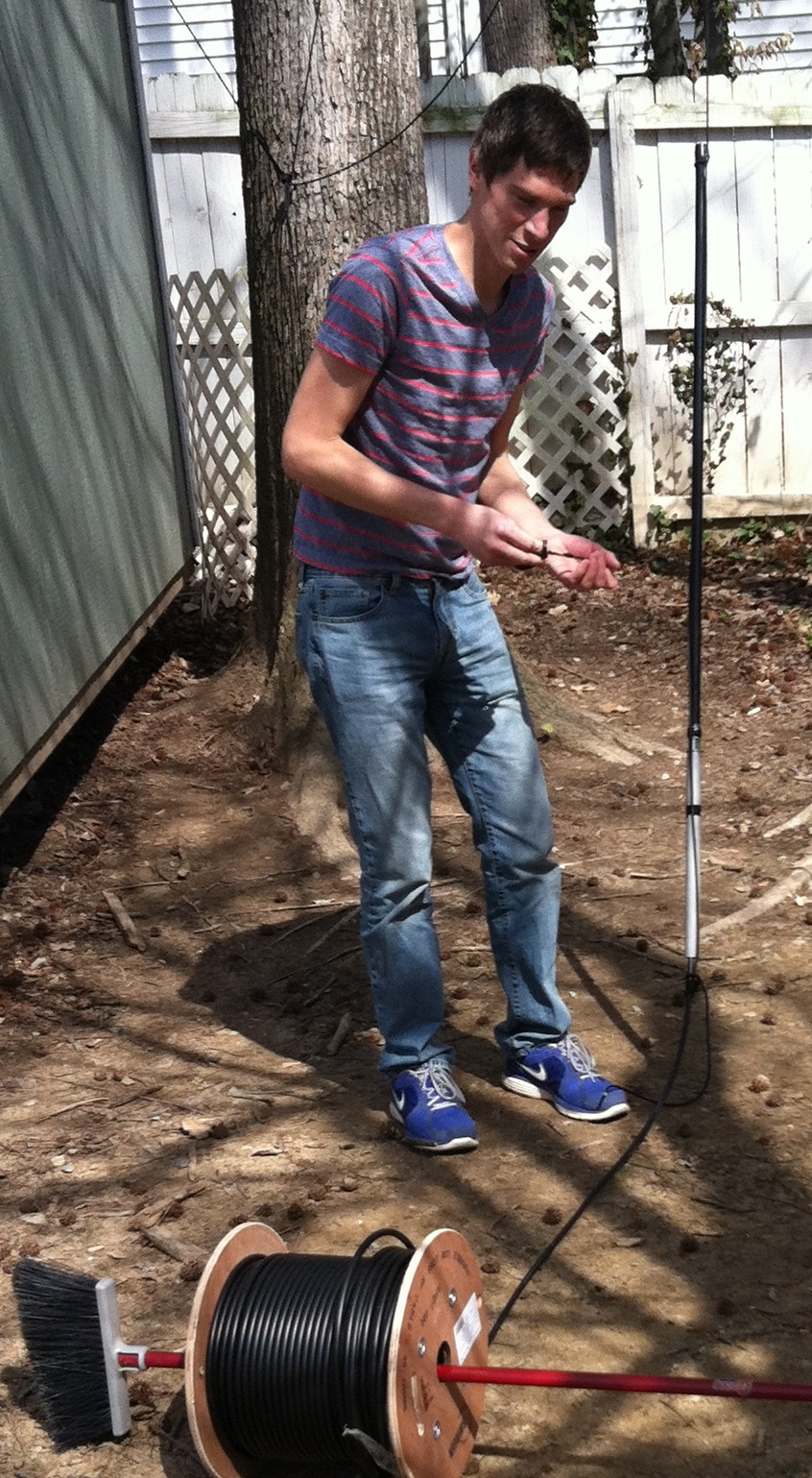
Your coax should be on a spool about 20' away from under falling branches and the spool should be supported through a pipe or pole. Don't hurt your coax or your fingers.
Use the mason-twine to pull 550 paracord or equivalent.
Pull the 550 over the path of your mason-twine, and through an eye bolt screwed into the tree at the 6' level.
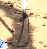
Tie the paracord to the coax at the bottom of the antenna.
I did that by wrapping the pully paracord around the coax several times and then I taped it, and then tied at the bottom of the antenna and then tied again at the top of the antenna.
The idea is that the strain of holding the coax weight is on the rope and not on the antenna's coax connector.
Now drag the antenna slowly up the tree while standing out of harms way!! (EXTREME falling branch hazard here) while your buddy stands well back out of falling branch range and makes sure the coax is unrolling properly.
You can guide the antenna by holding the coax, but don't put any more weight on it than you have to.
Walk back a couple of dozen (more) yards.
Take a photo of your work.
Now you can think about taking off your hard hats.
Austin antenna and roll of coax -- the hard hats are out of picture.
We just posed for this picture after lunch and before we pulled the antenna up.
Austin 144/220/440 antenna 80' up in tree
Click to zoom in
Antennas for hanging
I'm kind of partial to the Diamond X50a, Diamond X300a, Comet GP-3 and Comet GP-6 antenna now.
The Austin seemed neat at the time but it's performance wasn't very good on any band but 6m.
The more complex Diamond and Comet antennas have much more gain for the size.
The Austin antenna's two claims to desirability were that it had 4 bands in one tube, and that it was just a vertical dipole on each band so it was not very sensitive to nearby foliage.
Note on complex omni antennas: A colinear antenna, or any antenna more complicated than a 1/4 wave ground plane or half wave dipole, needs to be kept away from foliage.
You should have a clear foliage-free space around the antenna keeping clear about one wave length around the sides of the vertical antenna.
Above or below isn't too bad, but next to can change the performance of the antenna.
Stay away from J-poles at packet stations.
They tend to put some amount of RF into the hamshack, putting voltages on wires, and interfering with other receivers.
This might be permissable in a single-operator station, but a packet node can have assynchronous operation of multiple radios symultaneously and common-mode-currents can cause some issues.
Beware of the cheap immitation antennas.
Some of them may be great, but some of them use really crappy hardware and cut corners everywhere.
It's likely your antenna will work as designed but the advertising may be completely dishonest, and the antenna may be hard to work with, age badly, and not be as tollerant of abuse, as the Diamond and Comet brands.
Diamond and Comet have good after-sales support in the USA.
The big difference between the Chinese brands and the Japanese brands isn't their point of manufacture.
It's the design quality control, production quality control, the honesty of the advertising, the quality of the documentation, and the availability of support.


 Gigaparts has very competitive prices.